Ductwork airtightness
What is ductwork airtightness?
Ductwork airtightness can be defined as the resistance to inward or outward air leakage through the ductwork shell. The limit values for the maximum air leakage volume flow in duct systems are defined in the 4 tightness classes A to D which is now transformed into 7 new Air Tightness Classes ATC 1 – ATC 7 in different European standards, e.g. EN 12599, EN 16798-3, EN12237or EN1507.
See also
How is the ductwork airtightness quantified?
There are two major systems to classify ductwork airtightness, one based on European standards, the other one based on ASHRAE standard 90.1-2010. Both are based on the leakage airflow rate at a given ductwork pressure divided by the product of the ductwork surface area and the same ductwork pressure raised to the power 0.65.
In Europe, airtightness classes of ductwork components/fittings are defined in European Standard EN 12237 for circular ductworks, EN 1507 for rectangular ductworks and EN 17192 for non-metallic ductworks. Airtightness of components ranges from class A to D, with class A being the leakiest one. EN 1751 and EN 15727 specify the leakage requirements for technical ductwork components and are based on the same leakage classification. Airtightness classes for air handling units (L1 to L3) are defined in EN 1886.
Airtightness classes for ductwork systems are defined in EN 16798-3:2017 (EPBD standard). In 2017, EN 16798-3 introduced new names for ductwork airtightness classes; ductwork systems now range from classes ATC 7 to ATC 1. The Table that follows provides the correspondence (equivalence) between airtightness classes A to D and the new names ATC 7 to ATC 1. The leakage test method for system commissioning is described in EN 12599.
In the US, leakage classes 48, 24, 12, 6, 3 as defined by ASHRAE are commonly used; ASHRAE also gives recommended acceptance criteria based air leakage as a percentage of fan design airflow at maximum operating conditions.
The new classes are called ATC (Air tightness classes)
| ATC new | ATC old |
Limit value air leakage fmax (m³/s) |
| ATC 7 | ||
| ATC 6 | 2.5xA |
0,0675 • pt0,65• 10-3 |
| ATC 5 | A | 0,027 • pt0,65• 10-3 |
| ATC 4 | B | 0,009 • pt0,65• 10-3 |
| ATC 3 | C | 0,003 • pt0,65• 10-3 |
| ATC 2 | D | 0,001 • pt0,65• 10-3 |
| ATC 1 | 0,00033 • pt0,65• 10-3 |
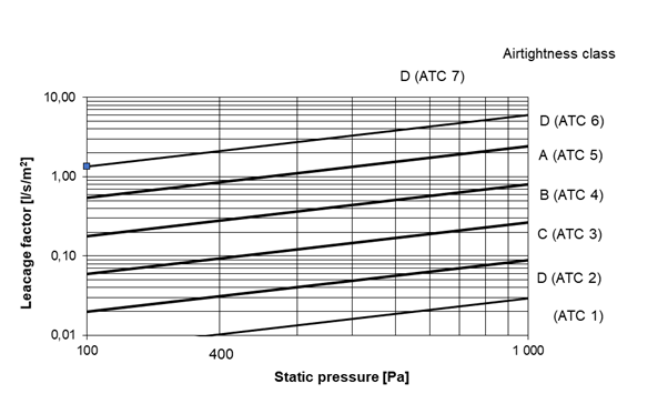
The new and old classes are valid but the old A-D will eventually be withdrawn.
All the metallic duct standards EN1505, EN1506, EN1507, EN 12237 and EN 14239 for certification and purchasing phase of the building will soon be merged to one standard and also include these new ATC classes.
See also
What is the energy impact of ductwork airtightness?
When a ductwork is leaky, part of the flowrate generated by the fan comes from (for extract ductwork) or goes through (for supply ductwork) leakages instead of air terminal devices (ATDs). If the fan compensates at least partially for leakage (with either higher fan power or a longer operating time) this will lead to an increase in fan energy use.
Moreover in countries where air is often the carrier of the thermal distribution, leakages also induce an increase of heating and cooling load.
Calculations and measurements performed in various studies (presented in a VIP dedicated to ductwork airtightness) show that improving ductwork airtightness may reduce the fan energy use from 30% to 75%. The impact of leakages on heating loads is estimated between 5% and 18% and between 10% and 29% for cooling loads; with also a high impact on the cooling design power that can be increased by 48% if leakages are considered.
When a ductwork is leaky, part of the flowrate generated by the fan comes from (for extract ductwork) or goes through (for supply ductwork) leakages instead of air terminal devices (ATDs). Therefore, the fan needs to move more air to compensate for the extra flowrate and the extra pressure losses due to leakages. If air flows are not increased to compensate for leakage, then the required flowrates are not met at ATDs which may lead to a poor indoor air quality (IAQ). On the other hand, if the fan compensates at least partially for leakage (with either higher fan power or a longer operating time) this will lead to an increase in fan energy use.
Moreover in countries where air is often the carrier of the thermal distribution, leakages also induce an increase of heating and cooling load.
Additional fan energy use to compensate ductwork leakage
The fan power consumption depends upon the flowrate produced by the fan and the pressure difference on either side of the fan:
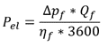
with:
- Pel (W): Electrical power of the fan
- Δpf (Pa): Pressure difference at fan
- Qf (m3/h): Flowrate at fan
- ηf : Efficiency of the fan (may depend on the pressure difference and flow rate)
The higher the pressure drop (resistance) in the ductwork, the higher the pressure difference the fan needs to produce to overcome this resistance and achieve the hygienic flow rate. So, leakages can be compensated by a higher fan power or by a longer operating time to achieve the same average indoor contaminant level. Both will increase energy use.
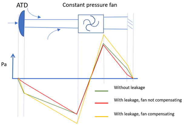
Pressure profiles along a simple extract ductwork are illustrated below [1] for three cases :
- without leakages;
- with leakages not compensated by the fan: the pressure drop is reduced at the ATD, inducing a lower airflow rate (poor indoor air quality);
- with leakages compensated by the fan: same pressure drop as 1) at the ATD to meet a hygienic airflow rate which requires an increased fan pressure (increased energy use).
Calculation and measurements performed in various studies are summarised in [1] and show that reducing ductwork airtightness may reduce the fan energy use from 30% to 75%.
Additional heating and cooling loads due to losses of preconditioned air
In the US, air is often the carrier of the thermal distribution. A study from 2005 indicated that 10%–30% of the conditioned air in an average central air conditioning system escapes from the ducts [2]. Therefore, the main concern in the US, regarding ductwork leakages, is the loss of preconditioned air.
Indeed, leakages also induce an increase of heating and cooling loads as:
- when leakages occur in a conditioned space this may lead to over-ventilation;
- when the air is pre-conditioned and leakages of the supply ductwork occur outside the conditioned space, the pre-conditioned air is not fully used for the building (lost heated or cooled air);
- when there is a heat exchanger, leakages of the extract ductwork in an unconditioned space decrease the energy recovery;
- when the air is pre-cooled, a secondary impact of the increased fan power is an increase in the cooling load associated with the heat generated from the increased fan power [3].
As both calculation (depending on the building's energy performance and on the climate) and measurements (with leakages mingling with conductions losses) are challenging, few studies estimate the impact of ductwork leakages on heating and cooling loads (summarised in the VIP). The impact of leakages on heating loads is estimated between 5% and 18% and between 10% and 29% for cooling loads. The highest impact seems to be on the cooling design power that can be increased by 48% if leakages are considered.
References
[1] Leprince V., Hurel N. and Kapsalaki M.,2020. VIP 40 Ductwork airtightness – A review. AIVC, April 2020
[2] Srinivasan, K., 2005. Measurement of air leakage in air-handling units and air conditioning ducts. Energy and Buildings , 37, 273–277.
[3] Modera, M., 2005. Fixing duct leaks in commercial buildings. ASHRAE journal, 22-28.
See also
What is the impact of duct leakage on comfort, ventilation, indoor air quality and fire security?
Duct leakage is not only detrimental to energy efficiency, but also to indoor air quality (in terms of lower air change rates and ventilation efficiency in rooms), comfort, fire protection, noise, dust accumulation, moisture damage or even contamination issues.
When the fan compensates for ductwork leakage by generating higher pressure and flow rates, energy losses are induced. When the fan does not (or only partially) compensate for leakage, the hygienic flow rate is not reached at every air terminal device, inducing indoor air quality (IAQ) issues especially in rooms located far away from the fan.
In a pandemic context, one can note that air leakage in extract ducts can also spread contaminants such as viruses to other parts of the building. Leaks located downstream the filter and upstream the fan can lead to polluted air bypassing the filter, leading to poor IAQ issues.
In Scandinavia good ductwork airtightness has largely been promoted together with indoor air quality benefits. Note that the Swedish VVS AMA guideline not only deals with energy issues related to ductwork airtightness but also with safety and indoor environment. [1].
In [2], other effects than energy losses and IAQ issues are reported, such as changes in noise that tends to increase with increasing duct flows [3]. Leakages can have 3 noise related effects:
- Increasing fan flowrate and pressure needed will increase the noise produced by the fan
- Leaks can also increase the transmission of fan sound pressure
- Leaks can create their own “whistling” noise
It is also believed that leakages can increase dust accumulation in filters [4], heat exchangers and ducts, as there is more flow rate going through.
Moreover, ductwork leakages lead to uncontrolled airflows that may induce depressurization causing backdrafting of combustion equipment or pressurisation causing moisture damage in walls [5]. This unbalance may also weaken contamination protection of sensitive areas (operating theatres, clean rooms, etc.)
Finally, fire-rated ventilation ducts can avoid fire and heat spread between two building compartments, but this can be compromised by ductwork leakage.
References
[1] Guyot, G., and Carrié, F.R., 2010. Stimulation of good building and ductwork airtightness through EPBD. ASIEPI, 2010.
[2] Leprince V., Hurel N., and Kapsalaki M.,2020. VIP 40 Ductwork airtightness – A review. AIVC, April 2020
[3] Richieri, F., et al., 2018. Ductwork design flaws and poor airtightness: a case study about a ventilation system reconditioning in a sealed building. Proceedings of the 39th AIVC-7 th TightVent-5 th venticool Conference, 18-19 September, Juan-Les-Pins, France. pp. 442-451.
[4] Dyer, David F., 2011. Case study: Effect of excessive duct leakage in a large pharmaceutical plant. Proceedings of the 32nd AIVC & 1st TightVent Conference, 12- 13 October. Brussels, Belgium. pp. 55-56.
[5] Modera, M., 2005. Fixing duct leaks in commercial buildings. ASHRAE journal, pp. 22- 28.
See also
Is it possible to improve the airtightness of a ductwork after completion?
To improve the air tightness of existing air ducts, a method of sealing the ducts by applying a sealant using a spray atomizer was developed in the USA in the early 2000s and is now (since 2015) being used in Europe. This method [1] can reduce leakage in an installed air duct system by 66-86% and can therefore improve the air tightness after installation. This can have other positive side effects, such as the impact on energy costs, indoor air quality & comfort or hygienic requirements.
References
[1] MEZ-AEROSEAL. https://www.mez-technik.de/en/mez-aeroseal.html
How is a ductwork airtightness test performed?
The ductwork airtightness test is made by attaching a measured airflow to the system and measure the static pressure inside. The idea is that the flow going in is the same as the leakage when the pressure is stable. The leakage flow is then divided by the ductwork surface area so that a big system can be compared with a small system. The procedure is similar to building airtightness test but with less flow, other pressures, other size criteria and limits.
Ductwork air tightness can be tested for certification and purchasing purposes described in:
- EN 12237 for circular metallic ducts
- EN 1507 for rectangular metallic ducts
- EN 15727 for technical components
- EN 17192 for nonmetallic ducts
and for a fully installed system in:
- EN 12599 for handing over a ventilation system
All standards have the same mathematical equations to define the limits for the airtightness classes. The limit is defined as the leakage flow at a certain pressure. The leakage flow is also defined at 1m² surface area so that a big system can be compared with a small system.
It is easy to calculate the surface area for a system which is simplified to the length of the centerlines at each dimension multiplied with the circumference. The standards have also taken a normal system into consideration and limited the amount of joints. If a system has an exceptional amount of joints compared to a normal system the system is out of scope and can not be defined in the standards. The definition of normal systems is different for example in metallic and non metallic standards.
For single components it is more difficult to define the surface area because some products are small and some large. Here the area is defined as a virtual area with 1 meter duct on the product. It becomes even more complicated when a product has more than 2 joints which are different in size or the product has no joints like an access door.
The actual test is made by attaching a measured airflow to the system and measure the static pressure inside. The idea is that the flow going in is the same as the leakage when the pressure is stable.
For certification of the product/system the supplier has to state a span of pressures that the system will work and test several pressures between the limits. In the ready built system the test is preferably done at the pressure that is going to be in the system when used. It can also be tested at a predefined pressure like in Sweden it is always 400 Pa positive pressure then it is easy to compare and perform.
See also
What are the requirements for a calibration in terms of traceability and quality?
A calibration should be carried out by an ISO/IEC 17025 accredited lab. Sometimes in some specific context it is allowed to have the calibration done by:
- a lab that has standards traceable to ISO/IEC 17025 accredited calibrations
- the manufacturer
- the user of the instrument
There are no general requirements, each country has its own regulations and the extent to which it is an advice, recommendation or obligation also varies from country to country. The calibration must, at the very least, demonstrate compliance with the factory specifications of the device.
References
- International Organization for Standardization,"ISO/IEC 17025: 2017. General requirements for the competence of testing and calibration laboratories", 2017.
See also
What quality frameworks exist in Europe for ductwork airtightness testers?
To our knowledge, in Europe there is only the French qualification Qualibat 8721 for ductwork airtightness testers.
In Sweden, there is a requirement for a mandatory inspection of the ventilation system (OVK) to be carried out by a certified expert functional inspector, but airtightness is normally not a part of that scope.
How to implement tight ductwork
An important point for improving the air tightness of air ducting systems is the use of ducts with factory-fitted air-tight connections with flat gaskets [1]. Furthermore, to install tight air ducts, not only the installation itself is crucial, but also upstream processes and participants in planning (e.g. selection of the right standard), manufacturing (e.g. selection of sheet thicknesses) and transport (e.g. load securing and fixing of components) play a significant role.
In order to comply with the required European standards, care must generally be taken when handling the air duct parts.
The air duct parts:
- must be transported conscientiously and stored cleanly.
- must not be pushed over the connecting flange.
- must be visually inspected for damage before starting installation.
- no usage when damaged.
The following instructions must be observed during installation:
- Depending on the air tightness class requirement, apply the duct sealing tape crosswise in the corner area and to the inner edge of the connecting profile. The tape may only be used once, i.e. after dismantling the air duct parts, the sealing tape must be replaced in order to reuse these parts.
- The profile flanges must be screwed to the corner screw connections and checked again for strength after approx. 48 hours.
- From an edge length of > 500mm (depending on the air tightness class and operating pressure), threaded clamps or sliding strips (min. 100mm long) must be fitted evenly over the edge length of the flange. The use must be adapted to the respective conditions and tested.
- Symmetrical suspension of the ductwork must be maintained to ensure air tightness.
- Fitting parts are delivered with loose frames (depending on the air tightness class provisionally with sheet metal friction bolts (tightness class A) or loose (class B, C, D)). After shortening the component, the frame must be fitted and then fastened and sealed. Fixing and sealing must be carried out in accordance with the requirements of the construction site or design specifications (pressure rating, tightness class).
- A tightness test cannot be passed in case of defective execution of the mounting.
- The installation has an influence on the tightness of the duct system of far more than 50%.
- The final air tightness of the duct system is in the hands and therefore the responsibility of the installation company [2].
References
[1] Leprince V., Hurel N. and Kapsalaki M.,2020. VIP 40 Ductwork airtightness – A review. AIVC, April 2020
[2] Installation instructions for ductwork. 2015
What is the impact of pressure drop on the result of ductwork airtightness test?
Inside a ductwork a flow rate undergoes pressure drop due to friction and dynamic losses. Numerical models [1] were set and experiments were conducted [2] to determine the impact of those pressure losses on the result of a ductwork airtightness test. It has been shown that, for airtight ductwork (class C) the impact of pressure losses on the measured flow rate is expected to be very small. Nevertheless, for very leaky ductwork it would be good practice to determine (through calculation described in [1]) the maximal length to be tested (distance between the measuring device and the farthest end of the ductwork) or to check in various locations the homogeneity of the pressure.
References
[1] Berthault S. & Leprince V., 2019. Reliability of ductwork airtightness measurement: impact of pressure drop and leakage repartition on the test result . 40th AIVC Conference “From Energy crisis to sustainable indoor climate – 40 years of AIVC", Ghent, Belgium, 15-16 October 2019
[2] Berthault S., Boithias F., & Leprince V., 2014. Ductwork airtightness: reliability of measurements and impact on ventilation flowrate and fan energy consumption. 35th AIVC Conference "Ventilation and airtightness in transforming the building stock to high performance", Poznań, Poland, 24-25 September 2014
Can ductwork airtightness test equipment be used to test building airtightness?
Duct tester systems designed to conduct air tightness tests on duct systems can sometimes be used to test building air tightness. The fans used in these systems have a much lower flow capacity than a standard blower door system, which means the building would have to be tight enough to accommodate the fan. This typically requires deliberate planning for air tightness and proper installation of air sealing materials. There are blower door kits available that use a duct tester fan that include a cloth with a smaller hole to accommodate that type of fan.
Are there databases of ductwork airtightness?
There are two ductwork airtightness databases that are often discussed in literature [1]:
- the French database from CEREMA: this database was created in 2016, it includes all the tests performed in France by a qualified tester in a regulatory or Effinergie certification context (1,300 ductwork airtightness measurements in 2018) [2]. The public agency, CEREMA, is in charge of the data collection and annual analysis of the database (which is not public).
- the US database from Lawrence Berkeley National Laboratory (ResDB): The LBNL Residential Diagnostics Database (ResDB) contains both envelope and duct leakage measurements for US homes (public database). There are approximately 30 000 duct leakage data until 2012 including total duct leakage and duct leakage to outside with details on buildings characteristics: type of home; state; year built; floor area; etc. [3]
References:
[1] Leprince V., Hurel N. and Kapsalaki M., 2020. VIP 40 Ductwork airtightness – A review. AIVC, April 2020
[2] Moujalled B., Leprince V., Melois A. Statistical analysis of about 1,300 ductwork airtightness measurements in new French buildings: impacts of the type of ducts and ventilation systems. 39th AIVC conference ”Smart ventilation for buildings”, Sep 2018, Antibes Juan-Les-Pins, France
[3] Chan W.R., Joh J., Sherman M.H. Analysis of Air Leakage Measurements from Residential Diagnostics Database. LBNL Report, Aug 2012
What are relevant CEN standards related to ductwork airtightness?
TightVent Europe has published a list of applicable standards for building and ductwork airtightness. The detailed list can be found here.
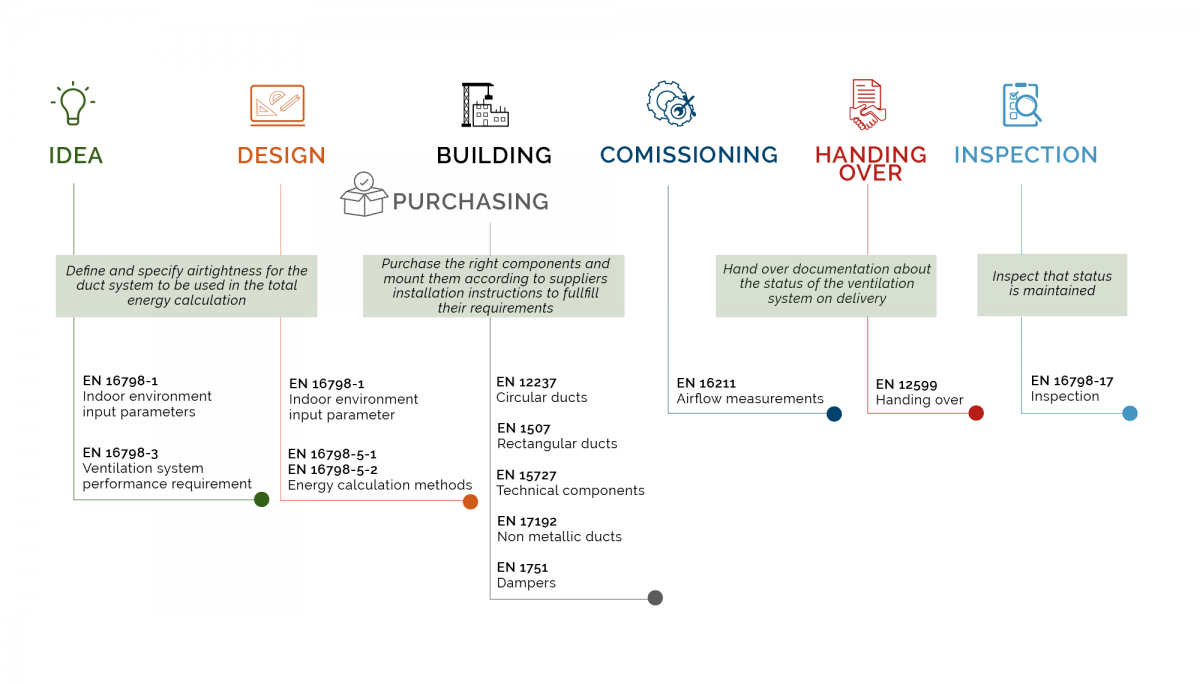
The graph below shows ductwork airtightness standards in relation to the design and construction process.
How do you design for ductwork airtightness?
Leakage in ventilation duct systems is important to keep to a minimum in order to save energy and keep the designed performance for a good indoor air quality. The tightness can be built by quality products and a professional installation or be sealed off afterwards by a sealant which is transformed into a gaseous state using heated compressed air. The aerosolized particles then seal the whole leakage of the ventilation system.
To design ventilation duct fittings in the proper way it is important to have the right shape on each product both after production but also during transport and handling. Each product has to have purpose designed seals, all seals like tape or mastic made on the installation site are extremely hard to achieve in a professional manner.
The ducts and duct fittings like bends, connectors or transformations are normally not so difficult to achieve and there are some certification programs that guarantee that the system is the promised quality. Technical components like dampers, silencers, filter boxes are normally a bit more difficult and are sometimes produced by a company only focusing on this specific component where no certification program is available. In 2010 the standard EN 15727 Duct and ductwork components, leakage classification and testing was developed to help the ventilation business focus on airtightness for the whole system even if the components are produced by different suppliers.
The installation will be focused on in the standard EN 12599 handing over and the design and calculation will be addressed in EN 16798-3 performance requirements of ventilation.
At the installation phase it is important to follow the supplier installation instructions and use the proper recommended sealings, screws and clamps the right way. To test air tightness during the installation before the system is built in or insulated is also wise to be able to fix any possible problem. To have the installer himself test the system during the work will be very educational and will lead to professional, fast and insightful staff.
Is building airtightness testing mandatory?
Requirements depend on the country and the context of the measurement. Most EU countries include in their regulations either required or recommended minimum airtightness levels with or without mandatory testing. There are several countries (e.g.United Kingdom, France, Belgium, Ireland) where, by regulation, airtightness testing is mandatory for certain building types or in the case of specific programmes [1].
References
[1] Leprince V., Kapsalaki M., & Carrié F., R., “VIP 37: Impact of Energy Policies on Building and Ductwork Airtightness”. AIVC, 2017.
What sort of certification programmes for ductwork airtightness exist?
Eurovent Certita Certification have a certification programme for rigid and semi-rigid ventilation ductwork systems divided into the following sub-programmes:
- Rigid metallic ductwork systems with circular cross-section (DUCT-MC);
- Rigid metallic ductwork systems with rectangular cross-section (DUCT-MR);
- Semi-rigid non-metallic ductwork systems predominantly made of plastics (DUCT-P);
Each sub-programme applies to ductwork systems fitted with integrated sealing solution as described in the Technical Certification Rules ECP-19.
This programme contains amongst other, airtightness and static gauge pressure limit criteria and is based on European standards.
The certification process is to periodically check the resilience of the company quality system by auditing manufacturing sites and the certified performances of a ventilation system by a third-party laboratory measurement.
The certification brings the supplier products, its technical documentation and quality resilience to a reliable level.
The DUCT program does not cover other types of ventilation ductwork elements like flexible ducts, double-wall ductwork or ductwork made of insulation ductboards.
The Swedish type approval for metallic ducts has been a very important driver for the ventilation business. The requirement based vision has driven the ventilation business since the beginning of the 1970’s to sustainable solutions with demands on airtightness and strength without a demand for sheet steel thickness. This has led to airtight energy efficient duct work solutions with as little material as possible.
The Swedish Type approval issued by governmental Boverket is only valid in Sweden but has been widely used in other countries as well. There are two Swedish bodies accredited by SWEDAC to issue type approvals, RISE and Kiwa.
Finland has developed their own approval based on the Swedish type approval and is handled by the Finnish Ministry of Environment, and Eurofins Expert Service Oy is authorized by the Finnish Ministry of Environment to issue type Approvals for building products.
What is an airtightness/air leakage testing? What is fan pressurization?
A method of quantifying how much air leaks into or out of an enclosure. EN 13829 gives a standard test method for buildings. Several standards apply to ductwork systems (see also “How is the ductwork airtightness quantified?“).
Building airtightness levels can be measured by using a fan, temporarily installed in the building envelope (a blower door) to pressurize the building. Air flow through the fan creates an internal, uniform, static pressure within the building. The aim of this type of measurement is to relate the pressure differential across the envelope to the air flow rate required to produce it. Generally, the higher the flow rate required to produce a given pressure difference, the less airtight the building [1].
[1] M. Limb, “Technical note AIVC 36- Air Infiltration and Ventilation Glossary,” International Energy Agency energy conservation in buildings and community systems programme, 1992.
What is TAAC? How can I be involved?
TAAC is the TightVent Airtightness Associations Committee, launched in September 2012 by the TightVent Europe platform, with the primary goal to bring together national associations and experts in order to promote reliable testing/inspection and reporting procedures.
The scope of TAAC includes various aspects such as: building & ductwork airtightness requirements in the countries involved; competent tester schemes in the countries involved; applicable standards and guidelines for testing; inspection of ventilation systems; collection of relevant guidance and training documents; share of knowledge and experience; and information on ongoing research work in the field of building and ductwork airtightness.
At present the participants are from Belgium, Czech Republic, Estonia, France, Germany, Hungary, Ireland, Latvia, Netherlands, Poland, Portugal, Spain, Sweden, Switzerland, UK and the US.
In case you are interested to join this initiative, please write an email to: info@tightvent.eu.
Links:
For more information please see:
- About TAAC: https://tightvent.eu/taac
- TAAC participants: https://tightvent.eu/taac/taac-participants
- TAAC deliverables (publications, webinars etc.): https://tightvent.eu/taac/deliverables
- Becoming a Tightvent partner (for companies): https://tightvent.eu/contact
- Becoming a TAAC member: https://tightvent.eu/taac/contact-join
The text and images of this webpage is available for modification and reuse under the terms of the Creative Commons Attribution-Sharealike 3.0 Unported License and the GNU Free Documentation License (unversioned, with no invariant sections, front-cover texts, or back-cover texts).