What is building airtightness?
Building airtightness (also called envelope airtightness) is a general descriptive term expressing the resistance to inward or outward air leakage through unintentional leakage points or areas in the building envelope. This air leakage is driven by differential pressures across the building envelope due to the combined effects of stack, external wind and mechanical ventilation systems [1]. The smaller the air leakage rate at a given pressure difference across a building envelope, the greater the airtightness [2].
In standards [3] as well as publications for non-experts, building airtightness is also called air permeability of buildings.The terms however are not synonymous: the more airtight the envelope, the less permeable it is.
References
[1] G. Guyot, F. R. Carrié and P. Schild, “Project ASIEPI – Stimulation of good building and ductwork airtightness through EPBD,” 2010.
[2] AIVC Technical Note 36. Air Infiltration and Ventilation Glossary. 1992.
[3] ISO 9972:2015 Thermal performance of buildings – Determination of air permeability of buildings – Fan pressurization method
What are the methods to detect leaks of the building envelope?
Detecting the location of leakages in the building envelope is useful in order to reduce the leakage area of the envelope and/or to estimate the leakage distribution of buildings [2]. Blower doors are very useful to find leaks [1].
The usual procedure consists of creating with the blower door an underpressure from approximately 50 Pa and checking the complete building envelope. This is done for example by walking around from room to room in the house while the blower door is running and feeling the incoming air with a hand. Sometimes it is useful to use a wet hand, because evaporative cooling makes it more sensitive. It is possible to open and close single interior doors in order to get an idea of the leakage from individual rooms. The worst rooms are usually the ones that have plumbing or those with connections to attics, crawl spaces and garages.
Several methods are possible for leak detection, listed below from gross to fine:
- Visual inspection of specific parts of the constructions like wall-roof connections.
- Inspection of the building envelope while the blower door creates 50 Pa negative pressure in the building and locate leaks with your hand.
- Thermal-Anemometry is a very reliable tool to locate air flows at 50 Pa negative pressure. It can be held against places of the building envelope or devices where one might suspect leakages. If the instrument shows an air velocity, it is an indication of leakage [2].
- During 50 Pa leakage test (depressurization), a thermal camera can be used to localize air infiltration as long as there is a temperature difference between indoor and outdoor. The infrared image shows the heating or cooling of the surface near the leakage caused by the incoming air flow. Sometimes this kind of temperature change on surfaces can also be observed due to the natural pressure difference caused by wind or stack effect.
- Smoke from a smoke generator in combination with a blower door creating a pressurization or depressurization can help to find leaks. The smoke is generated to visualize the airflow through the envelope, devices, etc. and to detect the location of the leakage. In some cases it is also possible to find the way – the leak path – how the air moves through the envelope.
- There are systems available that use ultrasonic sound to get detailed qualitative information on leaks around windows, doors, walls/roof connections. Some research has been done to also use ultrasonic sound to quantify leakages [3]
References
[1] Allison A. Bailes III, PhD, "A House Needs to Breathe … Or Does It? An introduction to Building Science" (page 111: “Using a Blower Door to Find Leaks”), Bright Communications, October 2022.
[2] International Organization for Standardization, "ISO 9972:2015. Thermal performance of buildings — Determination of air permeability of buildings — Fan pressurization method", 2015
[3] Benedikt Kölsch et al., "Quantification of air leakage paths: a comparison of airflow and acoustic measurements", International Journal of Ventilation 22(6), August 2021.
See also:
- Designing Buildings, "Draughts in buildings" , Retrieved 30 June 2023
- Designing Buildings, "Leaks in buildings", Retrieved 30 June 2023
What are the requirements in European countries regarding ductwork airtightness?
Very few countries have mandatory requirements for ductwork airtightness. In Europe this is the case for Spain and Estonia.
Spain has the strongest requirements, with a maximum ductwork permeability of ATC 4 for all new and retrofitted buildings according to “Reglamento de instalaciones térmicas de los edificios” (RITE) since 2007, with a mandatory justification by test according to UNE-EN 12599:01 to prove compliance. However, the authors mentioned that in practice ductwork is not always tested and there are no sanctions if a ductwork does not comply with the requirements.
In Estonia, the requirements for ventilation systems in buildings require class ATC 4 (class B) or better for the whole system and recommend ducts and components of Class C or better. The requirements for the airtightness class of the ventilation ductwork are usually set by the ventilation designer based on the specific requirements of the building or room. the airtightness test is not always mandatory, and it depends on the customer’s requirements and designer’s requirements in HVAC Project.
More details can be found in the AIVC Technical Note 73 [1].
References
[1] N. Hurel and V. Leprince “AIVC Technical Note 73 – Overview of the trends in building and ductwork airtightness in 16 countries”, AIVC Ventilation Technical Report, Sept 2024, Available: https://www.aivc.org/sites/default/files/TN73.pdf
What is a building airtightness test?
A building airtightness test is a method for directly measuring the air leakage rate created by leakages in a building enclosure or component.
A building airtightness test is a method for directly measuring the amount of airflow created by leakages in a building enclosure.
There are a number of ways to measure the airtightness (see FAQ ‘What are existing methods to estimate building airtightness? Are there other test methods apart from fan pressurisation?’, but the most common method is the fan pressurisation test.
In this case, a measurement is taken of the air flow rate required to pressurise or depressurise an enclosure, in order to quantify the air leakages of the envelope of the enclosure. A fan, temporarily installed in the enclosure, (also called a blower door, see FAQ ‘What is a Blower Door?’) is used to pressurise or depressurise the enclosure to a known and controlled pressure with respect to outdoors, usually up to 50 to 100 Pascal.
This allows for a stable investigative environment, as this induced pressure is usually enough to negate any stack effect and wind induced pressures.
The aim of this type of measurement is to relate the pressure differential across the building envelope to the air flow rate required to produce it, in order to quantify the building airtightness. The higher the flow rate required to produce a given pressure difference, the less airtight the enclosure. [1].
References
[1] M. Limb, “Technical note AIVC 36- Air Infiltration and Ventilation Glossary,” International Energy Agency energy conservation in buildings and community systems programme, 1992. Available at: https://www.aivc.org/resource/tn-36-air-infiltration-and-ventilation-glossary?volume=33978
See also
What building airtightness requirements exist in different countries?
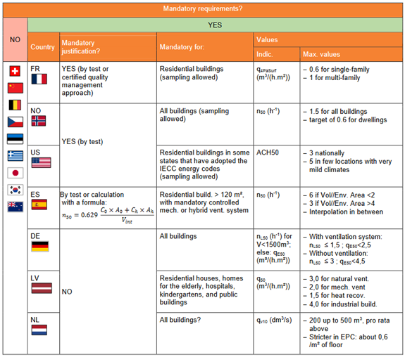
The most direct way for countries to ensure good building airtightness is to define mandatory requirements with maximum allowable air leakage. This is done by some countries such as Norway, Germany and the Netherlands for all buildings, and France, Spain, Latvia and the USA for certain types of buildings only, with in general a focus on residential buildings. To ensure that the airtightness requirements are met, a mandatory justification is asked for only 3 of these countries: France, Norway and the USA.
The maximum air permeability values are defined depending on different parameters according to the countries: single/multi-family buildings in France; dwellings/other buildings in Norway; the envelope area in Spain; the type of ventilation systems in Germany and Latvia; the building volume in the Netherlands and the location (different value for very mild climates) in the USA.
The required airtightness level for these countries are given in the table below, more details can be found in the AIVC Technical Note 73 [1] from which this table comes.
References
[1] N. Hurel and V. Leprince “AIVC Technical Note 73 – Overview of the trends in building and ductwork airtightness in 16 countries”, AIVC Ventilation Technical Report, Sept 2024, Available: https://www.aivc.org/sites/default/files/TN73.pdf
What are existing methods to estimate building airtightness? Are there other test methods apart from fan pressurization?
Existing methods to estimate building airtightness include:
- Fan pressurization, multi point test
- Fan pressurization, single point test
- Pulse test
- Tracer gas test
Fan pressurization, multi point [1],[2]
From a multi point pressurization test the airflow through the leakages in the building envelope is measured at different building pressures differences. A blower door uses a fan to depressurize or pressurize the building envelope. Both a multi point and a single point test can be carried out with the blower door. From the multipoint test a leakage graph with flow coefficient and leakage exponent can be generated in order to calculate air leakage rates at different building pressure differences (e.g. at 50 Pa, 4 Pa etc.) to determine for example the air change rate of a building. This measurement method is described in ISO 9972:2015.
With a single point test it is possible to get a rough estimation of the airflow at a certain building pressure difference. The fan is adjusted to the target pressure and the air flow is read to determine a value of interest (e.g. the air change rate at 50 Pa). The blower door method is extensively described in the FAQ "What is a blower door?".
1-point measurement using the home's ventilation system [3]
A method developed in the Netherlands uses the ventilation system to pressurize the building.The instrument consists of a reference vessel fitted with a valve and a differential pressure meter. Before the start of the measurement the valve is open and the ventilation system is off. At the start of the measurement the valve closes. While the ventilation system is switched on and off several times, the pressure difference between the building and the reference vessel is measured. From this pressure difference in combination with the ventilation volume flow, the air permeability is determined. The time required for the 1-point measurement is limited (approximately 10 minutes). The preparations and conditions of the building or building section to be tested are the same as for the determination with a blower door. As mentioned already, for a single point measurement the flow exponent must be chosen.
The Pulse test [4], [5]
The pulse test was developed in the UK. The measuring principle of the pulse test (Jens Couckuyt, 2018) is: "The device contains an air tank with a certain capacity, e.g 60 liters. The vessel must be charged by a compressor. During the measurement a known volume of air is sent out for one and a half seconds. This causes a short rise (pulse) in the air pressure. This pressure rise provides airflow through the air leaks. Over time the pressure difference will be stabilized again. The pressure difference, during two seconds before and after the air pressure pulse, is also recorded by the device. The container must be refilled after the test. The measurement result is calculated at a pressure difference of 4 Pa. The pressure range that is achieved is not the same for every test. It depends on the pressure in the air tank, the air leakage and the volume of the building".
Tracer gas test [6], [7]
This test method entails introducing a small amount of tracer gas into a structure, thoroughly mixing it, and measuring the rate of change (decay) in tracer concentration. The air change rate can be estimated from the decay rate of tracer concentration with respect to time. Onsite meteorological conditions are measured concurrently. In the on-site monitor variant, tracer concentrations as a function of time are measured on site as air samples are obtained. In the container sample variant, after the tracer gas has thoroughly mixed, an initial air sample container is filled. The tracer gas is allowed to decay for a period of several hours during which a second and perhaps third sample container is filled. The air change rate can be determined from the decay in tracer concentrations.
References
[1] International Organization for Standardization, "ISO 9972:2015. Thermal performance of buildings — Determination of air permeability of buildings — Fan pressurization method", 2015
[2] David Keefe, "Introduction to Blower Doors", Home Energy. January/February 1994.
[3] T. Lanooy, W. Kornaat, N-J. Bink , W. Borsboom, "A new method to measure building airtightness", 39th AIVC Conference "Smart Ventilation for Buildings", Antibes Juan-Les-Pins, France, 18-19 September 2018.
[4] Jens Couckuyt, "Experimenteel onderzoek bij luchtdichtheidsmetingen: vergelijkende studie tussen traditionele Blowerdoor en vernieuwende Pulse test". Ghent University, 2018.
[5] E. Cooper, X. Zheng, C. Wood, M. Gillot, D. Tetlow, S. Riffat, L. De Simon, "Field trialling of a new airtightness tester in a range of UK homes", 36th AIVC Conference " Effective ventilation in high performance buildings", Madrid, Spain, 23-24 September 2015.
[6] ASTM, "Standard test method for determining air leakage rate by tracer dilution", ASTM Designation E 741-83, August 1987.
[7] M.H. Sherman, "Tracer-gas techniques for measuring ventilation in a single zone", Building and Environment, Vol 25, No 4, pp 365-374,1990.
[8] A. Vega Pasos , X. Zheng, V. Sougkakis , M. Gillott , J. Meulemans , O. Samin , F. Alzetto , L. Smith , S. Jackson , C. J. Wood, "Experimental study on the measurement of Building Infiltration and Air Leakage rates (at 4 and 50 Pa) by means of Tracer Gas methods, Blower Door and the novel Pulse technique in a Detached UK Home", 39th AIVC Conference "Smart Ventilation for Buildings", Antibes Juan-Les-Pins, France, 18-19 September 2018.
[9] M.J. Limb, "TN 55: A Review of International Ventilation, Airtightness, Thermal Insulation and Indoor Air Quality Criteria", AIVC Technical Note 55, 2001
See also
- Corbett Lunsford, "Tracer Gas Test", Home performance, YouTube, 2018
What is ductwork airtightness?
Ductwork airtightness can be defined as the resistance to inward or outward air leakage through the ductwork shell. The limit values for the maximum air leakage volume flow in duct systems are defined in the 4 tightness classes A to D which is now transformed into 7 new Air Tightness Classes ATC 1 – ATC 7 in different European standards, e.g. EN 12599, EN 16798-3, EN12237or EN1507.
See also
What is infiltration/exfiltration?
Infiltration/exfiltration is the uncontrolled inward/outward leakage of outdoor/indoor air through air permeable materials, joints, cracks, interstices and other unintentional openings of a building envelope, caused by the pressure effects of wind, the stack effect or operation of HVAC-systems [1]. Infiltration/exfiltration causes convective heat and moisture transfer, resulting in excessive heat loss and potential moisture problems in the building envelope. The building airtightness measurement aims at finding, quantifying and reducing those unintentional cracks and openings in order to get the intended airtightness of the building.
References
[1] Limb. M.,1992. “Technical note AIVC 36- Air Infiltration and Ventilation Glossary” International Energy Agency energy conservation in buildings and community systems programme, 1992.
See also
How is the building airtightness quantified?
The airtightness of a building is quantified by means of the measured air leakage rate through the building’s envelope in m³/h at a given reference pressure difference, often 50 Pa. The building airtightness may be expressed by other quantities, derived from the air leakage rate at a reference pressure difference, and normalised using, for example, one of the following measures for the size of the building:
- Internal building volume V. At 50 Pa, the associated indicator is called air change rate at 50 Pa and noted n50 [unit h-1].
- Envelope area AE. At 50 Pa, the associated indicator is called air permeability at 50 Pa and noted qE50 (former: q50 in EN 13829) [unit m3/(h.m2)[.
- Net floor area AF. At 50 Pa, the associated indicator is called specific leakage rate and noted qF50, (former: w50 in EN 13829) [unit m3/(h.m2)].
Other indicators of airtightness exist in national regulations.
How is the ductwork airtightness quantified?
There are two major systems to classify ductwork airtightness, one based on European standards, the other one based on ASHRAE standard 90.1-2010. Both are based on the leakage airflow rate at a given ductwork pressure divided by the product of the ductwork surface area and the same ductwork pressure raised to the power 0.65.
In Europe, airtightness classes of ductwork components/fittings are defined in European Standard EN 12237 for circular ductworks, EN 1507 for rectangular ductworks and EN 17192 for non-metallic ductworks. Airtightness of components ranges from class A to D, with class A being the leakiest one. EN 1751 and EN 15727 specify the leakage requirements for technical ductwork components and are based on the same leakage classification. Airtightness classes for air handling units (L1 to L3) are defined in EN 1886.
Airtightness classes for ductwork systems are defined in EN 16798-3:2017 (EPBD standard). In 2017, EN 16798-3 introduced new names for ductwork airtightness classes; ductwork systems now range from classes ATC 7 to ATC 1. The Table that follows provides the correspondence (equivalence) between airtightness classes A to D and the new names ATC 7 to ATC 1. The leakage test method for system commissioning is described in EN 12599.
In the US, leakage classes 48, 24, 12, 6, 3 as defined by ASHRAE are commonly used; ASHRAE also gives recommended acceptance criteria based air leakage as a percentage of fan design airflow at maximum operating conditions.
The new classes are called ATC (Air tightness classes)
| ATC new | ATC old |
Limit value air leakage fmax (m³/s) |
| ATC 7 | ||
| ATC 6 | 2.5xA |
0,0675 • pt0,65• 10-3 |
| ATC 5 | A | 0,027 • pt0,65• 10-3 |
| ATC 4 | B | 0,009 • pt0,65• 10-3 |
| ATC 3 | C | 0,003 • pt0,65• 10-3 |
| ATC 2 | D | 0,001 • pt0,65• 10-3 |
| ATC 1 | 0,00033 • pt0,65• 10-3 |
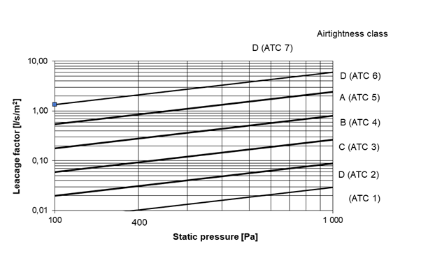
The new and old classes are valid but the old A-D will eventually be withdrawn.
All the metallic duct standards EN1505, EN1506, EN1507, EN 12237 and EN 14239 for certification and purchasing phase of the building will soon be merged to one standard and also include these new ATC classes.
See also
What are the most common air leakage/infiltration paths?
Air penetrates through porous building materials and through joints in the building structure, therefore, airtight construction techniques must focus on these aspects. Different construction materials exhibit different leakage characteristics. Irrespective of construction material, a modern building is normally of double skin construction in which the inner and outer leaves are separated by a layer of insulation. Air-tightness is dependent on good sealing of the inner leaf by means of an air barrier system. [1]
With air barrier systems in place, key air infiltration paths to address are the interfaces between building components, most importantly interfaces between windows and walls, and between walls and roof or floors. [2]
Common leakage sites are listed in Figure 1 below. Figure 2 gives the classification of these sites in 4 categories [3]:
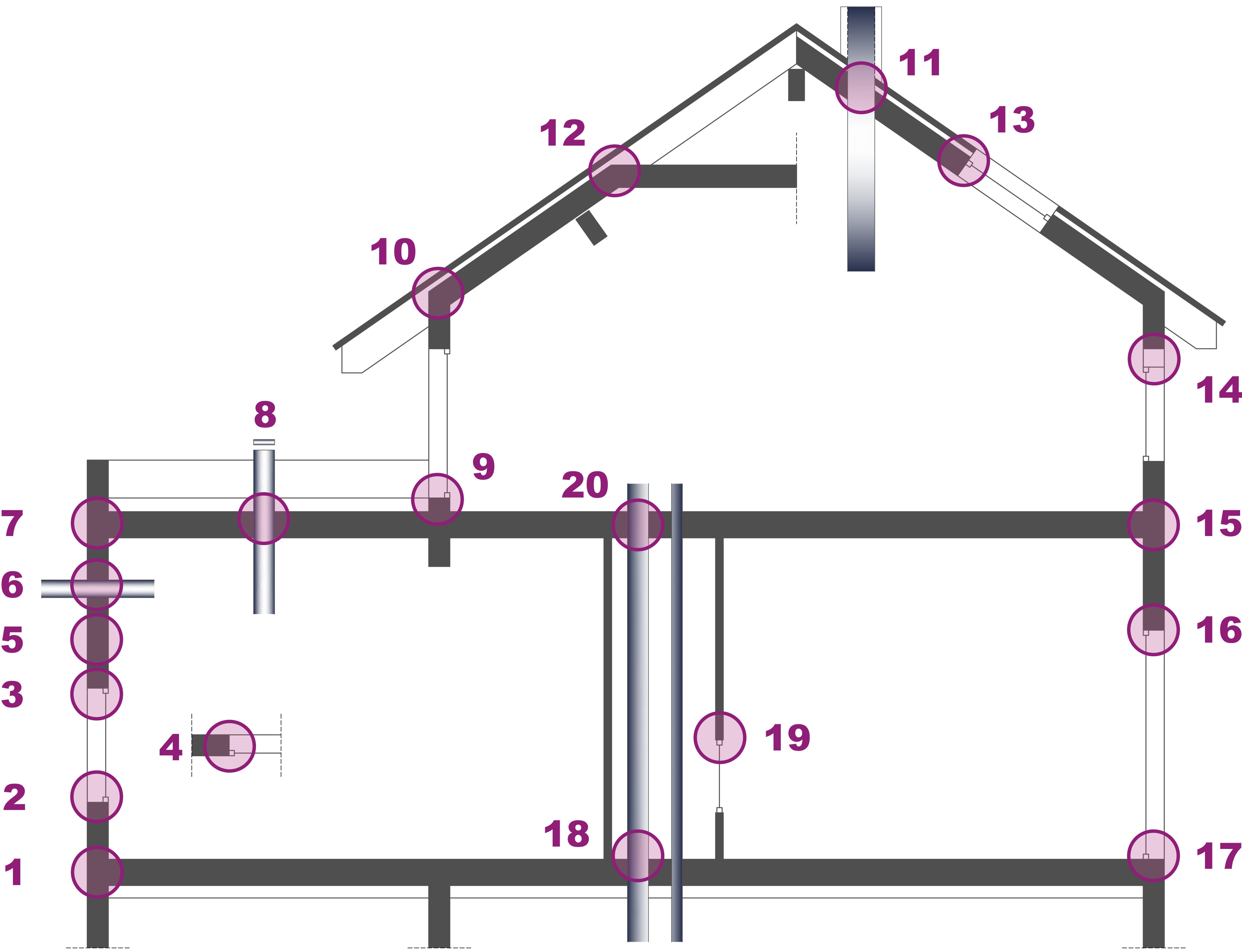
Figure 1: Vertical section of a typical building with identification of potential leakage junctions (Source: CEREMA – Pôle QERA)
- Junction lower floor / vertical wall
- Junction window sill / vertical wall
- Junction window lintel / vertical wall
- Junction window reveal / vertical wall (horizontal view)
- Vertical wall (Cross section)
- Perforation vertical wall
- Junction top floor / vertical wall
- Penetration of top floor
- Junction French window / vertical wall
- Junction inclined roof / vertical wall
- Penetration inclined roof
- Junction inclined roof / roof ridge
- Junction inclined roof / window
- Junction rolling blind / vertical wall
- Junction intermediate floor / vertical wall
- Junction exterior door lintel / vertical wall
- Junction exterior door sill / sill
- Penetration lower floor / crawlspace or basement
- Junction service shaft / access door
- Junction internal wall / intermediate floor

Figure 2: Common leakage sites classified in 4 categories (Source: CEREMA – Pôle QERA)
References
[1] Liddament M., 1996. Guide to energy efficient ventilation. AIVC, 1996.
[2] Van Den Bossche N., et al. 2011. Airtightness of the window-wall interface in cavity brick walls. Energy and Buildings. DOI: 10.1016/j.enbuild.2011.10.022
[3] Carrié F.R., Jobert R., and Leprince V., “Contributed Report 14- Methods and techniques for airtight buildings” AIVC, 2012.
The text and images of this webpage is available for modification and reuse under the terms of the Creative Commons Attribution-Sharealike 3.0 Unported License and the GNU Free Documentation License (unversioned, with no invariant sections, front-cover texts, or back-cover texts).
What is the energy impact of ductwork airtightness?
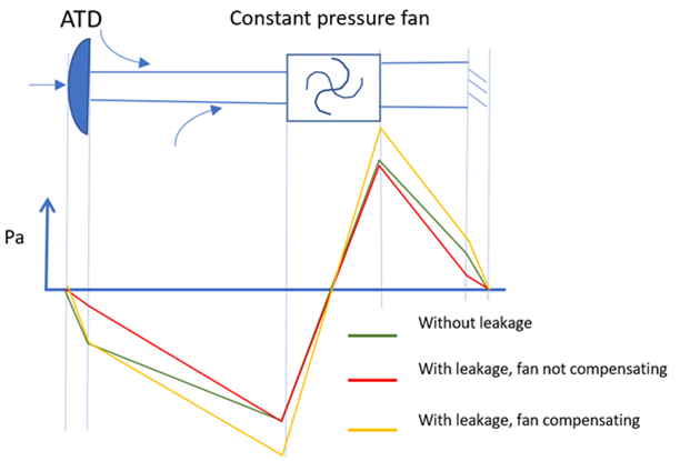
When a ductwork is leaky, part of the flowrate generated by the fan comes from (for extract ductwork) or goes through (for supply ductwork) leakages instead of air terminal devices (ATDs). If the fan compensates at least partially for leakage (with either higher fan power or a longer operating time) this will lead to an increase in fan energy use.
Moreover in countries where air is often the carrier of the thermal distribution, leakages also induce an increase of heating and cooling load.
Calculations and measurements performed in various studies (presented in a VIP dedicated to ductwork airtightness) show that improving ductwork airtightness may reduce the fan energy use from 30% to 75%. The impact of leakages on heating loads is estimated between 5% and 18% and between 10% and 29% for cooling loads; with also a high impact on the cooling design power that can be increased by 48% if leakages are considered.
When a ductwork is leaky, part of the flowrate generated by the fan comes from (for extract ductwork) or goes through (for supply ductwork) leakages instead of air terminal devices (ATDs). Therefore, the fan needs to move more air to compensate for the extra flowrate and the extra pressure losses due to leakages. If air flows are not increased to compensate for leakage, then the required flowrates are not met at ATDs which may lead to a poor indoor air quality (IAQ). On the other hand, if the fan compensates at least partially for leakage (with either higher fan power or a longer operating time) this will lead to an increase in fan energy use.
Moreover in countries where air is often the carrier of the thermal distribution, leakages also induce an increase of heating and cooling load.
Additional fan energy use to compensate ductwork leakage
The fan power consumption depends upon the flowrate produced by the fan and the pressure difference on either side of the fan:
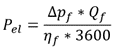
with:
- Pel (W): Electrical power of the fan
- Δpf (Pa): Pressure difference at fan
- Qf (m3/h): Flowrate at fan
- ηf : Efficiency of the fan (may depend on the pressure difference and flow rate)
The higher the pressure drop (resistance) in the ductwork, the higher the pressure difference the fan needs to produce to overcome this resistance and achieve the hygienic flow rate. So, leakages can be compensated by a higher fan power or by a longer operating time to achieve the same average indoor contaminant level. Both will increase energy use.
Pressure profiles along a simple extract ductwork are illustrated below [1] for three cases :
- without leakages;
- with leakages not compensated by the fan: the pressure drop is reduced at the ATD, inducing a lower airflow rate (poor indoor air quality);
- with leakages compensated by the fan: same pressure drop as 1) at the ATD to meet a hygienic airflow rate which requires an increased fan pressure (increased energy use).
Calculation and measurements performed in various studies are summarised in [1] and show that reducing ductwork airtightness may reduce the fan energy use from 30% to 75%.
Additional heating and cooling loads due to losses of preconditioned air
In the US, air is often the carrier of the thermal distribution. A study from 2005 indicated that 10%–30% of the conditioned air in an average central air conditioning system escapes from the ducts [2]. Therefore, the main concern in the US, regarding ductwork leakages, is the loss of preconditioned air.
Indeed, leakages also induce an increase of heating and cooling loads as:
- when leakages occur in a conditioned space this may lead to over-ventilation;
- when the air is pre-conditioned and leakages of the supply ductwork occur outside the conditioned space, the pre-conditioned air is not fully used for the building (lost heated or cooled air);
- when there is a heat exchanger, leakages of the extract ductwork in an unconditioned space decrease the energy recovery;
- when the air is pre-cooled, a secondary impact of the increased fan power is an increase in the cooling load associated with the heat generated from the increased fan power [3].
As both calculation (depending on the building's energy performance and on the climate) and measurements (with leakages mingling with conductions losses) are challenging, few studies estimate the impact of ductwork leakages on heating and cooling loads (summarised in the VIP). The impact of leakages on heating loads is estimated between 5% and 18% and between 10% and 29% for cooling loads. The highest impact seems to be on the cooling design power that can be increased by 48% if leakages are considered.
References
[1] Leprince V., Hurel N. and Kapsalaki M.,2020. VIP 40 Ductwork airtightness – A review. AIVC, April 2020
[2] Srinivasan, K., 2005. Measurement of air leakage in air-handling units and air conditioning ducts. Energy and Buildings , 37, 273–277.
[3] Modera, M., 2005. Fixing duct leaks in commercial buildings. ASHRAE journal, 22-28.
See also
What is the energy impact of building airtightness?
Poor building airtightness results in excessive air infiltration and resultant uncontrolled energy loss. The energy use increase is dependent on the infiltration flow rate and the amount of conditioning of the air that is necessary to achieve thermal comfort. The infiltration flow rate depends on the building airtightness and natural driving forces by wind and stack effect. For the same building airtightness, the energy impact is larger when the building is more exposed to high wind speeds and large temperature differences, and when the building is higher.
As an approximation, an increase of the air permeability of the building envelope with 1 m³/(h.m²)@50Pa has a similar energy impact as an increase of the average building envelope thermal transmittance (U-value) with 0.02 W/(m²K).
The Building Research Establishment in the UK has published an experimental study showing which energy savings are achievable with improved airtightness [1].
References
[1] R. Coxon, “Research into the effect of improving airtightness in a typical UK dwelling,” The REHVA European HVAC Journal-Special issue on airtightness, vol. 50, no. 1, pp. 24-27, 2013.
What is the impact of duct leakage on comfort, ventilation, indoor air quality and fire security?
Duct leakage is not only detrimental to energy efficiency, but also to indoor air quality (in terms of lower air change rates and ventilation efficiency in rooms), comfort, fire protection, noise, dust accumulation, moisture damage or even contamination issues.
When the fan compensates for ductwork leakage by generating higher pressure and flow rates, energy losses are induced. When the fan does not (or only partially) compensate for leakage, the hygienic flow rate is not reached at every air terminal device, inducing indoor air quality (IAQ) issues especially in rooms located far away from the fan.
In a pandemic context, one can note that air leakage in extract ducts can also spread contaminants such as viruses to other parts of the building. Leaks located downstream the filter and upstream the fan can lead to polluted air bypassing the filter, leading to poor IAQ issues.
In Scandinavia good ductwork airtightness has largely been promoted together with indoor air quality benefits. Note that the Swedish VVS AMA guideline not only deals with energy issues related to ductwork airtightness but also with safety and indoor environment. [1].
In [2], other effects than energy losses and IAQ issues are reported, such as changes in noise that tends to increase with increasing duct flows [3]. Leakages can have 3 noise related effects:
- Increasing fan flowrate and pressure needed will increase the noise produced by the fan
- Leaks can also increase the transmission of fan sound pressure
- Leaks can create their own “whistling” noise
It is also believed that leakages can increase dust accumulation in filters [4], heat exchangers and ducts, as there is more flow rate going through.
Moreover, ductwork leakages lead to uncontrolled airflows that may induce depressurization causing backdrafting of combustion equipment or pressurisation causing moisture damage in walls [5]. This unbalance may also weaken contamination protection of sensitive areas (operating theatres, clean rooms, etc.)
Finally, fire-rated ventilation ducts can avoid fire and heat spread between two building compartments, but this can be compromised by ductwork leakage.
References
[1] Guyot, G., and Carrié, F.R., 2010. Stimulation of good building and ductwork airtightness through EPBD. ASIEPI, 2010.
[2] Leprince V., Hurel N., and Kapsalaki M.,2020. VIP 40 Ductwork airtightness – A review. AIVC, April 2020
[3] Richieri, F., et al., 2018. Ductwork design flaws and poor airtightness: a case study about a ventilation system reconditioning in a sealed building. Proceedings of the 39th AIVC-7 th TightVent-5 th venticool Conference, 18-19 September, Juan-Les-Pins, France. pp. 442-451.
[4] Dyer, David F., 2011. Case study: Effect of excessive duct leakage in a large pharmaceutical plant. Proceedings of the 32nd AIVC & 1st TightVent Conference, 12- 13 October. Brussels, Belgium. pp. 55-56.
[5] Modera, M., 2005. Fixing duct leaks in commercial buildings. ASHRAE journal, pp. 22- 28.
See also
What sort of certification for building airtightness products exist?
Overall most of products are tested according to EN12114 (air permeability of building components) or EN 1026 (airtightness of windows) either internally or externally.
The most known way of certifying products is through Passive House Institute in Germany [1], the product, including installation manual, is sent to PHI Darmstadt, where THEY apply the product and assess it on its airtightness properties. A yearly fee has to be paid to maintain the certificate.
Another possibility would be to get a Komo certificate for the Dutch market (thus rather limited to Holland) or to go for quality stamps such as a Sintef approval (with some authority outside of Norway too).
There is also the MO01, a German directive written by IFT (Institut für Fenstertechnik) which enables to assess airtightness of perimeter joints around a window before and after ageing. The ageing is based on pressure, temperature and mechanical load.
References
[1] Passive House Institute. Components Database. Airtightness systems.
Is it possible to improve the airtightness of a ductwork after completion?
To improve the air tightness of existing air ducts, a method of sealing the ducts by applying a sealant using a spray atomizer was developed in the USA in the early 2000s and is now (since 2015) being used in Europe. This method [1] can reduce leakage in an installed air duct system by 66-86% and can therefore improve the air tightness after installation. This can have other positive side effects, such as the impact on energy costs, indoor air quality & comfort or hygienic requirements.
References
[1] MEZ-AEROSEAL. https://www.mez-technik.de/en/mez-aeroseal.html
How is a ductwork airtightness test performed?
The ductwork airtightness test is made by attaching a measured airflow to the system and measure the static pressure inside. The idea is that the flow going in is the same as the leakage when the pressure is stable. The leakage flow is then divided by the ductwork surface area so that a big system can be compared with a small system. The procedure is similar to building airtightness test but with less flow, other pressures, other size criteria and limits.
Ductwork air tightness can be tested for certification and purchasing purposes described in:
- EN 12237 for circular metallic ducts
- EN 1507 for rectangular metallic ducts
- EN 15727 for technical components
- EN 17192 for nonmetallic ducts
and for a fully installed system in:
- EN 12599 for handing over a ventilation system
All standards have the same mathematical equations to define the limits for the airtightness classes. The limit is defined as the leakage flow at a certain pressure. The leakage flow is also defined at 1m² surface area so that a big system can be compared with a small system.
It is easy to calculate the surface area for a system which is simplified to the length of the centerlines at each dimension multiplied with the circumference. The standards have also taken a normal system into consideration and limited the amount of joints. If a system has an exceptional amount of joints compared to a normal system the system is out of scope and can not be defined in the standards. The definition of normal systems is different for example in metallic and non metallic standards.
For single components it is more difficult to define the surface area because some products are small and some large. Here the area is defined as a virtual area with 1 meter duct on the product. It becomes even more complicated when a product has more than 2 joints which are different in size or the product has no joints like an access door.
The actual test is made by attaching a measured airflow to the system and measure the static pressure inside. The idea is that the flow going in is the same as the leakage when the pressure is stable.
For certification of the product/system the supplier has to state a span of pressures that the system will work and test several pressures between the limits. In the ready built system the test is preferably done at the pressure that is going to be in the system when used. It can also be tested at a predefined pressure like in Sweden it is always 400 Pa positive pressure then it is easy to compare and perform.
See also
What is calibration?
Calibration is the comparison of measurement values delivered by a device under test with those of a calibration standard of known accuracy. Such a standard could be another measurement device of known accuracy, a device generating the quantity to be measured such as a voltage, a sound tone, or a physical artifact, such as a meter ruler.
A calibration laboratory establishes whether the value given by a measuring instrument is correct in relation to the international unit of measurement. An ISO-17025 accreditation offers the best guarantee that this is indeed the case. Accreditation is granted for a specific area of work based on a specific, defined method. In accreditation, this is called the 'scope'.
Each European country has its own accrediting body. These organisations have a so-called Mutual Recognition Agreement (MRA) with each other, in Europe, and often beyond. In Europe there is an umbrella organisation called the European Cooperation for Accreditation (EA). This organisation ensures that accreditation is dealt with in the same way in all countries and that the same requirements apply everywhere. Certificates issued under accreditation in all these countries are therefore fully recognized and accepted in countries that have signed the MRA.
A guarantee of flawless work can never be given. Accreditation guarantees that "work is performed with the highest possible reliability". In order to continue to test this reliability, audits are carried out, with some regularity internal audits and at least once a year an external, independent audit is carried out by the accrediting body. Accredited laboratories are obliged to participate in proficiency testing, studies in which the test results of different laboratories are compared with each other.
The calibration of a blower door consists of 2 parts: a pressure calibration and a flow calibration. It is always recommended to make sure how these calibrations are performed. What kind of measurement setup is used and what are the measurement points? The scope (measured quantities, measuring method, ranges and uncertainties) of accredited labs can be found on the internet.
Links
- Directory of EA Members and MLA signatories – European Accreditation
-
International Organization for Standardization,"ISO/IEC 17025: 2017. General requirements for the competence of testing and calibration laboratories", 2017.
See also
What are the requirements for a calibration in terms of traceability and quality?
A calibration should be carried out by an ISO/IEC 17025 accredited lab. Sometimes in some specific context it is allowed to have the calibration done by:
- a lab that has standards traceable to ISO/IEC 17025 accredited calibrations
- the manufacturer
- the user of the instrument
There are no general requirements, each country has its own regulations and the extent to which it is an advice, recommendation or obligation also varies from country to country. The calibration must, at the very least, demonstrate compliance with the factory specifications of the device.
References
- International Organization for Standardization,"ISO/IEC 17025: 2017. General requirements for the competence of testing and calibration laboratories", 2017.
See also
What calibration is recommended for building airtightness measuring devices?
The recommended calibration for building airtightness measuring devices should follow the manufacturers recommendation as well as the governing body or standard being adhered to.
The recommended calibration for building airtightness measuring devices depends on the manufacturer's specifications. It is typically recommended to follow the calibration interval specified by the manufacturer, which is usually every 5 years. In addition, annual field calibration checks should be performed following the guidelines outlined in the manufacturer's blower door manual. The fan should retain its calibration as long as it has not been physically damaged, such as being dropped or fallen over. Manufacturers' manuals also provide guidance on checking the placement of the flow sensor or nacelle in the fan to ensure that it has not been moved since its original manufacture.
In some instances local, regional or national standards bodies will have differing recommendations to adhere to. This should be taken into consideration for calibration timelines.
In addition to the fan, it is also essential to consider the calibration of the digital pressure gauge. Typically, these devices should also follow the manufacturer's recommended calibration interval, which can vary from every 1, 3, or 5 years, depending on the device. It is important to reference the calibration requirements of the standard you are testing, in order to ensure accuracy. Field checks of the device should also be conducted by following the guidelines in the manufacturer's manual. Cross-checking the device with another recently calibrated gauge is also a recommended practice to ensure accuracy.
Furthermore, it is crucial to verify that the calibration facility holds the proper accredited scope to perform the calibration work. An ISO-17025 accredited lab is normal for calibrations in the air-tightness industry. This ensures that the calibration is performed to the highest standards and that the results are reliable and accurate.
Is good building airtightness compatible with good indoor air quality?
Yes, provided that the building is equipped with an appropriate ventilation system (whether natural, mechanical or hybrid). A French study mentioned in the AIVC newsletter n°2 shows that better building airtightness converges with better indoor air quality because the ventilation system operates more efficiently. Building leaks cause uncontrolled airflows and potentially poorly ventilated rooms although the total building air exchange rate may be sufficient [1].
[1] L. Mouradian and X. Boulanger, “QUAD-BBC, Indoor Air Quality and ventilation systems in low energy buildings,” AIVC Newsletter No2, June 2012.
What is the impact of wind on building airtightness test?
Wind creates a heterogeneous pressure distribution around the building and induces a pressure difference between indoor and outdoor even when the fan is turned off. The impact of wind can be partly compensated by measuring and subtracting this zero-flow pressure and by making the average between pressurization and depressurization test.
When we test a building for air tightness, a two-channel manometer is used to measure both the fan pressure on the blower door system and the pressure difference between indoor and outdoor. The building is either pressurized or depressurized by the blower door fan to create a measurable pressure differential that generates air flow through building’s leaks. This pressure differential is measured in units of Pascals (Pa).The impact of wind can be observed with the two-channel manometer and can sometimes make it difficult to get a stable, reliable reading since the wind causes the conditions outside to constantly fluctuate.
On windy days, leaks located downwind and upwind won’t have the same pressure difference. Therefore the flowrate through each leak will depend on its location on the building envelope: the impact of some leaks will be overestimated and some others will be underestimated.
Performing the test both in pressurization and depressurisation helps to limit the impact of wind on the result of the airtightness test.
Additionally, to account for windy conditions, a bias pressure (zero-flow pressure) is collected before the airtightness test. This is where the two-channel manometer collects a sample reading of the outdoor conditions for a given amount of time, usually 60 seconds. Some test standards require an additional bias pressure to be collected at the end of the test as well. The average pressure differential is then applied to the blower door results to remove the measured impact of wind, similar to the way we zero a scale before we weigh an object. Nevertheless, as the relation between flowrate and pressure is not linear, this subtraction is not sufficient to cancel the error.
Other recommendations exist but as stressed in [1] depend on standards, for example some texts recommend to smooth windy conditions with mechanical wind dampening where the outdoor reference tubing is branched into multiple sections with 90 degree turns.
This subject has been discussed in [1] and has been the subject of much research.
References
[1] Hurel N. & Leprince V., 2021. VIP 41: Impact of wind on the airtightness test results. AIVC, 2021
See also
- Bailly Mélois A. et al., 2019. Designing a model-scale experiment to evaluate the impact of steady wind on building air leakage measurements. 40th AIVC Conference “From Energy crisis to sustainable indoor climate – 40 years of AIVC", Ghent, Belgium, 15-16 October 2019
- Delmotte C., 2019. Airtightness of buildings – Considerations regarding place and nature of pressure taps. 40th AIVC Conference “From Energy crisis to sustainable indoor climate – 40 years of AIVC", Ghent, Belgium, 15-16 October 2019
- Bailly Mélois A. et al., 2018. Wind speed in building airtightness test protocols: a review. 39th AIVC Conference "Smart Ventilation for Buildings", Antibes Juan-Les-Pins, France, 18-19 September 2018.
- Leprince V., & Carrié F.R., 2017. On the contribution of steady wind to uncertainties in building pressurisation tests. 38th AIVC Conference "Ventilating healthy low-energy buildings", Nottingham, UK, 13-14 September 2017
- Peper S., & Schnieders J., 2019. Measurement of airtightness in high-rise structures. 11th International BUILDAIR Symposium, 24- 25 May 2019, Hannover, Germany
- Hsu Y-S.m 2019. Insights into the impact of wind on the Pulse airtightness test in a UK dwelling. 40th AIVC Conference “From Energy crisis to sustainable indoor climate – 40 years of AIVC", Ghent, Belgium, 15-16 October 2019
- Prignon M., Dawans A., & van Moeseke G., 2019. Quantification of uncertainty in zero-flow pressure approximation due to short-term wind fluctuations. 40th AIVC Conference “From Energy crisis to sustainable indoor climate – 40 years of AIVC", Ghent, Belgium, 15-16 October 2019
Are there organizations of airtightness testers?
There are various kind of airtightness tester organizations. Some organizations are led by the qualification scheme in the country for example the British ATTMA and iATS and the Belgian BCCA. In France Qualibat is in charge of the qualification process with about 1000 qualified testers and Syneole is the trade union for airtightness testers. Among other things, Syneole represents airtightness testers in standardization and regulation working groups and is part of the commission for tester qualification.
In Germany the association FLIB, more than 300 members, helps to improve both the implementation of airtightness and the measurement protocol by editing guidelines and contributing in standardization committee (such as for ISO 9972’s national annex).
There are also smaller associations of testers, such as the Association Blower Door CZ (A.BD_CZ) in the Czech Republic, gathering 21 members in 2022, which represents about half of the testers operating in the country. Its objective is also to improve measurement practice by performing round-robin tests with its members.
Since September 2012, TightVent hosts an airtightness associations committee (TAAC) with representatives of national/local associations or groups including, Syneole, A.BD_CZ, FLiB, iATS and ATTMA.
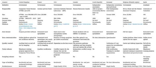
What quality frameworks exist in Europe for building airtightness testers?
In Europe, there are various quality frameworks to qualify building airtightness testers 1,2,3,4, including:
| Country |
Competent scheme operator |
Mandatory for testers? |
References |
| Belgium (Flanders) |
BCCA |
Yes | BCCA , [5] |
| Czech Republic |
A.BD_CZ (Association Blower Door CZ) |
No | A.BD_CZ |
| Denmark | DS certification | ? | |
| Finland | VTT Technical Research Center in Finland | ? | RATECO |
| France | Qualibat | Yes | Qualibat, [6] |
|
Germany |
FLiB (other certifications exist) | In particular programmes only | FliB, [7] |
| Greece | Aerosteganotita | No | Aerosteganotita |
| Ireland |
The National Standards Authority of Ireland- NSAI (95% of testers), The Irish National Accreditation Board – INAB & ATTMA (also recognised) |
Yes | NSAI, INAB (& ATTMA) |
| Japan | Institute for Building Environment and Energy Conservation | Yes | – |
|
Netherlands |
Under development (for now SKH uses a Belgian scheme) |
No | SKH |
| Sweden | Diplomerad Lufttäthetsprovare (Diploma air tightness tester) | No | ByggaL |
| UK |
Air Tightness Testing & Measurement Associations (ATTMA) & The Independent Airtightness Testing Scheme (iATS) |
No | |
| USA | RESNET |
In particular programmes only |
RESNET |
There are also many other countries in Europe that do not have a quality framework for airtightness testers (e.g. Spain, Poland or Estonia) but some testers choose to get a certification from one of the above listed quality frameworks. For example in Latvia it is estimated that there are approximately 8 persons qualified by the manufacturer programme Retrotec; 1 person qualified by FLiB (German Association for Airtightness) and 2 persons qualified by the Air Tightness Testing & Measurement Association (ATTMA).
References
[1] Carrié F.R, Wouters P., "AIVC TN 67: Building airtightness: a critical review of testing, reporting and quality schemes in 10 countries", AIVC, 2012
[2] Leprince V., Carrié F.R., Kapsalaki M., "Building and ductwork airtightness requirements in Europe – Comparison of 10 European countries", AIVC, 2017.
[3] Kalamees T., Hallik J., Mikola A., "AIVC VIP 45.1: Trends in building and ductwork airtightness in Estonia", AIVC, 2022.
[4] Hoek T., Poza-Casado I., Melgosa S., "AIVC VIP 45.2: Trends in building and ductwork airtightness in Spain", AIVC, 2022.
[5] De Strycker M., Van Gelder, L. Leprince V., "Quality framework for airtightness testing in the Flemish Region of Belgium – feedback after three years of experience", AIVC, 2018
[6] Leprince V., Carrié F.R., Olivier M., "The quality framework for Air-tightness measurers in France: assessment after 3 years of operation", AIVC, 2011
[7] Solcher O., "Quality system for airtightness measurement of buildings", AIVC, 2011
What quality frameworks exist in Europe for ductwork airtightness testers?
Very few countries have national qualification for ductwork airtightness testers. This is the case for France, the Netherlands (for utility buildings), and the USA. And among these countries, this qualification is mandatory only in France, in case the results are used for the Energy Performance calculation or to check compliance with labels’ requirements.
More details can be found in the AIVC Technical Note 73 [1]
References
[1] N. Hurel and V. Leprince “AIVC Technical Note 73 – Overview of the trends in building and ductwork airtightness in 16 countries”, AIVC Ventilation Technical Report, Sept 2024, Available: https://www.aivc.org/sites/default/files/TN73.pdf
How to implement tight ductwork
An important point for improving the air tightness of air ducting systems is the use of ducts with factory-fitted air-tight connections with flat gaskets [1]. Furthermore, to install tight air ducts, not only the installation itself is crucial, but also upstream processes and participants in planning (e.g. selection of the right standard), manufacturing (e.g. selection of sheet thicknesses) and transport (e.g. load securing and fixing of components) play a significant role.
In order to comply with the required European standards, care must generally be taken when handling the air duct parts.
The air duct parts:
- must be transported conscientiously and stored cleanly.
- must not be pushed over the connecting flange.
- must be visually inspected for damage before starting installation.
- no usage when damaged.
The following instructions must be observed during installation:
- Depending on the air tightness class requirement, apply the duct sealing tape crosswise in the corner area and to the inner edge of the connecting profile. The tape may only be used once, i.e. after dismantling the air duct parts, the sealing tape must be replaced in order to reuse these parts.
- The profile flanges must be screwed to the corner screw connections and checked again for strength after approx. 48 hours.
- From an edge length of > 500mm (depending on the air tightness class and operating pressure), threaded clamps or sliding strips (min. 100mm long) must be fitted evenly over the edge length of the flange. The use must be adapted to the respective conditions and tested.
- Symmetrical suspension of the ductwork must be maintained to ensure air tightness.
- Fitting parts are delivered with loose frames (depending on the air tightness class provisionally with sheet metal friction bolts (tightness class A) or loose (class B, C, D)). After shortening the component, the frame must be fitted and then fastened and sealed. Fixing and sealing must be carried out in accordance with the requirements of the construction site or design specifications (pressure rating, tightness class).
- A tightness test cannot be passed in case of defective execution of the mounting.
- The installation has an influence on the tightness of the duct system of far more than 50%.
- The final air tightness of the duct system is in the hands and therefore the responsibility of the installation company [2].
References
[1] Leprince V., Hurel N. and Kapsalaki M.,2020. VIP 40 Ductwork airtightness – A review. AIVC, April 2020
[2] Installation instructions for ductwork. 2015
What is the impact of pressure drop on the result of ductwork airtightness test?
Inside a ductwork a flow rate undergoes pressure drop due to friction and dynamic losses. Numerical models [1] were set and experiments were conducted [2] to determine the impact of those pressure losses on the result of a ductwork airtightness test. It has been shown that, for airtight ductwork (class C) the impact of pressure losses on the measured flow rate is expected to be very small. Nevertheless, for very leaky ductwork it would be good practice to determine (through calculation described in [1]) the maximal length to be tested (distance between the measuring device and the farthest end of the ductwork) or to check in various locations the homogeneity of the pressure.
References
[1] Berthault S. & Leprince V., 2019. Reliability of ductwork airtightness measurement: impact of pressure drop and leakage repartition on the test result . 40th AIVC Conference “From Energy crisis to sustainable indoor climate – 40 years of AIVC", Ghent, Belgium, 15-16 October 2019
[2] Berthault S., Boithias F., & Leprince V., 2014. Ductwork airtightness: reliability of measurements and impact on ventilation flowrate and fan energy consumption. 35th AIVC Conference "Ventilation and airtightness in transforming the building stock to high performance", Poznań, Poland, 24-25 September 2014
Can ductwork airtightness test equipment be used to test building airtightness?
Duct tester systems designed to conduct air tightness tests on duct systems can sometimes be used to test building air tightness. The fans used in these systems have a much lower flow capacity than a standard blower door system, which means the building would have to be tight enough to accommodate the fan. This typically requires deliberate planning for air tightness and proper installation of air sealing materials. There are blower door kits available that use a duct tester fan that include a cloth with a smaller hole to accommodate that type of fan.
Are there databases of building airtightness?
France, Belgium (Flemish Region) & the United Kingdom have national databases that gather most of measurements performed by qualified testers in their countries. Other initiatives also exist in Spain, Germany, Czech Republic, Estonia, Canada and the US ([1], [2], [3]).
- Spain (from the University of Valladolid): 400 tests data collected as a one-time effort for the INFILES Project, which represents a minor share of the total measured data.
- Germany (from The Association for Air Tightness in Buildings: FLiB e.V.)
- Czech Republic (from the Association Blower Door CZ: A.BD_CZ): 100 records per year which represents less than 6 % of the total amount of tests performed by the members
- Estonia (from the Tallinn University of Technology): There is no constantly updated database, the university has however collected and published measurement data several times
- Canada (Natural Resources Canada)
- the US (Lawrence Berkeley National Laboratory)
The table below is a summary of the main databases characteristics in Europe and North America ([3])
More information can be found in AIRBASE, the Bibliographic Database of the AIVC (e.g. search on “database”), as well as the Proceedings of AIVC & TightVent Joint conferences and workshops.
References
[1] V. Leprince, F. R. Carrié and M. Kapsalaki, “Building and ductwork airtightness requirements in Europe – Comparison of 10 European countries” in 38th AIVC Conference “Ventilating healthy low-energy buildings”, Nottingham, UK, 13-14 September 2017, Nottingham, 2017.
[2] V. Leprince, M. Kapsalaki, F. R. Carrié, “VIP 37: Impact of Energy Policies on Building and Ductwork Airtightness” AIVC, 2017.
[3] I. Poza-Casado, V.E.M. Cardoso, R.M.S.F. Almeida, A. Meiss, N.M.M. Ramos, M.Á. Padilla-Marcos, “Residential buildings airtightness frameworks: A review on the main databases and setups in Europe and North America”, Build. Environ. 183 (2020) 107221. https://doi.org/10.1016/j.buildenv.2020.107221.
Are there databases of ductwork airtightness?
There are two ductwork airtightness databases that are often discussed in literature [1]:
- the French database from CEREMA: this database was created in 2016, it includes all the tests performed in France by a qualified tester in a regulatory or Effinergie certification context (1,300 ductwork airtightness measurements in 2018) [2]. The public agency, CEREMA, is in charge of the data collection and annual analysis of the database (which is not public).
- the US database from Lawrence Berkeley National Laboratory (ResDB): The LBNL Residential Diagnostics Database (ResDB) contains both envelope and duct leakage measurements for US homes (public database). There are approximately 30 000 duct leakage data until 2012 including total duct leakage and duct leakage to outside with details on buildings characteristics: type of home; state; year built; floor area; etc. [3]
References:
[1] Leprince V., Hurel N. and Kapsalaki M., 2020. VIP 40 Ductwork airtightness – A review. AIVC, April 2020
[2] Moujalled B., Leprince V., Melois A. Statistical analysis of about 1,300 ductwork airtightness measurements in new French buildings: impacts of the type of ducts and ventilation systems. 39th AIVC conference ”Smart ventilation for buildings”, Sep 2018, Antibes Juan-Les-Pins, France
[3] Chan W.R., Joh J., Sherman M.H. Analysis of Air Leakage Measurements from Residential Diagnostics Database. LBNL Report, Aug 2012
What are relevant CEN standards related to building airtightness?
TightVent Europe has published a list of applicable standards for building and ductwork airtightness. The detailed list can be found here.
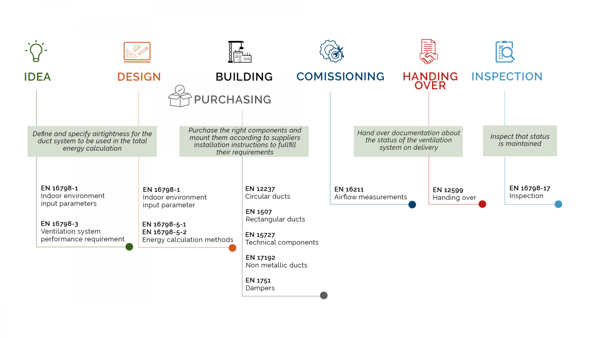
What are relevant CEN standards related to ductwork airtightness?
TightVent Europe has published a list of applicable standards for building and ductwork airtightness. The detailed list can be found here.
The graph below shows ductwork airtightness standards in relation to the design and construction process.
What do we know about the durability of building airtightness?
Airtightness durability is a growing issue in Europe and the US. In the long-term, it seems that some specific sealing products have durable performances but on-site studies have shown that many factors can deteriorate the airtightness durability of wall assemblies such as the association of incompatible products, poor implementation conditions, extreme wind loading or external interventions into the building envelope. As a result the global building airtightness seems to not be robust, and to deteriorate mostly in the first years after the construction.
Durability is investigated through laboratory and on-site studies. On site studies have shown that changes in building airtightness over time are very variable: for each study results differ considerably between the tested houses, with almost always at least one presenting an improved airtightness (by up to 40%) and almost always at least one presenting a very deteriorated airtightness (by up to 580%) compared to the initial airtightness test result.
Airtightness durability is a growing issue in Europe and the US. Various studies have been ongoing for the past 15 years as well as major projects (i.e. DURABILIT’AIR).
Some studies focus on laboratory tests to evaluate the durability of sealing products, in particular tapes with mechanical tests performed before and after artificial ageing. In Germany, a standard to test the durability of airtightness products in laboratory, DIN 4108-11, has been published at the end of 2018 and may be introduced as a project to CEN (European Committee for Standardization) to the T.C. (Technical Committee) 89.
Results of such laboratory tests give indication on the product performance. It is however not a guarantee that the building airtightness relying on these products will be durable as:
- there is no obvious correlation between the durability of the product alone and the assembly airtightness [1];
- laboratory conditions differ from on-site building conditions so that the measured performance may differ in practice from test results;
- natural ageing, with various load types (temperature, humidity, wind, UV, rain, etc.) occurring sometime simultaneously cannot be accurately reproduced with artificial ageing and is specific for each building;
- the product performance is usually measured through mechanical tests (peel and shear resistance measurement for example) such as in DIN 4108-11, which is not a direct air permeability measurement, and results may differ significantly [2].
On-site studies have also been carried out in the past decades to evaluate the buildings airtightness durability ([3]-[15]). Pressurization tests are performed both shortly after construction and some years later (from 1 to 25). The comparison between these airtightness measurements allow us to draw, for now, the following conclusions:
- Airtightness is not robust: Significant changes in air permeability with time are observed for at least part of the tested houses in all studies (except one study [10]). This is the case whatever the initial airtightness level, building age and building sample size.
- Airtightness tends to deteriorate after completion: The mean change in air permeability is positive for all studies.
- Changes in airtightness are very variable: For each study results differ considerably between the tested houses, with almost always at least one presenting an improved airtightness (by up to 40%) and almost always at least one presenting a very deteriorated airtightness (by up to 580%).
- Changes in airtightness occur quickly after construction: the mean change in measured air permeability does not seem to clearly increase with the building age, which would mean that changes occur mostly within the first (1 or 2) year(s) of the building use. This is suggested in the study with the largest sample size [8] and confirmed by a study with buildings tested regularly where air permeability increased mainly in the first years [6].
- Changes in airtightness in absolute terms seem correlated to the initial air permeability level: Changes in absolute terms are bigger for initially more permeable buildings. In other words, an initially very airtight building tends to have rather small additional air flow rates (in absolute term) compared to an initially leaky building.
- Changes in airtightness does not seem to strongly depend on the main construction material: both wooden and concrete constructions were sometimes found to have a durable airtightness and other times a strongly deteriorated airtightness.
These studies also point out various possible key factors of airtightness decrease over time:
- Building’s natural “movements”: Heating houses for the first time may induce the shrinkage of mastics and structure movements
- External interventions: Drilling hole into the envelope deteriorating the air barrier system; Installation of cables or ductwork after the completion of the building
- Specific building materials and construction types:
- Houses generally became leakier than the flats in [13]
- 2-storey houses seem to deteriorate more than 1-storey [8].
- Airtightness of houses with exposed wood frame roofs seems to deteriorate more than other roofs [8].
- Airtightness unchanged for houses with polyethene air barriers, but slightly degraded for houses built with the drywall approach in [5].
- Plasterboard-lining as an internal finish can result in very high leakage according to [16]
- Poor workmanship
- Unsuitable implementation conditions for adhesives and mastic such as cold and/or dusty conditions [17].
- Airtightness measurement conditions: building preparation and measurement uncertainty [3]. Especially if the two tests are not performed by the same people.
To conclude, in the long-term, it seems that some specific sealing products have durable performances but on-site studies have shown that many factors can deteriorate the airtightness durability of wall assemblies such as the association of incompatible products, poor implementation conditions or external interventions into the building envelope. As a result the global building airtightness seems to not be robust, and to deteriorate mostly in the first years after the construction.
References
[1] P. Ylmén, M. Hansén & J. Romild, "Durability of air tightness solutions for buildings", 35th AIVC Conference "Ventilation and airtightness in transforming the building stock to high performance", Poznań, Poland, 2014, p. 268‑278.
[2] E. B. Møller & T. V. Rasmussen, "Testing Joints of Air and Vapour Barriers, Do We Use Relevant Testing Methods?", XV International Conference on Durability of Building Materials and Components (DBMC 2020), Barcelona, Spain, 2020.
[3] W. Bracke, J. Laverge, N. Van Den Bossche & A. Janssens, "Durability and Measurement Uncertainty of Airtightness in Extremely Airtight Dwellings", International Journal of Ventilation, vol. 14, no 4, p. 383‑393, 2016, doi: 10.1080/14733315.2016.11684095.
[4] S. Verbeke & A. Audenaert, "A prospective Study on the Evolution of Airtightness in 41 low energy Dwellings", 12th Nordic Symposium on Building Physics (NSB 2020), E3S Web Conf., vol. 172, p. 05005, 2020, doi: 10.1051/e3sconf/202017205005.
[5] G. Proskiw, "The variation of airtightness of wood-frame houses over an 11-year period", Thermal performance of the exterior envelopes of buildings VII Conference, Clearwater Beach, Florida, 1998, p. 745-751\\r874.
[6] J. Novák, "Assessment of durability of airtightness by means of repeated testing of 4 passive houses", 39th AIVC Conference "Smart Ventilation for Buildings", Antibes Juan-Les-Pins, France, 2018.
[7] ADEME, "Quelle pérennité de la perméabilité à l'air des maisons individuelles BBC en Normandie?", 2016.
[8] B. Moujalled, V. Leprince, S. Berthault, A. Litvak & N. Hurel, "Mid-term and long-term changes in building airtightness: A field study on low-energy houses", Energy and Buildings, vol. 250, p. 111257, nov. 2021, doi: 10.1016/j.enbuild.2021.111257.
[9] W. Feist, W. Ebel, S. Peper, W. Hasper, R. Pfluger & M. Kirchmair, "25 Jahre Passivhaus Darmstadt Kranichstein", Darmstadt, 2016.
[10] S. Peper, O. Kah & W. Feist, "Long-time durability of passive house building airtightness", 38th AIVC Conference "Ventilating healthy low-energy buildings", Nottingham, UK, 2017, p. 13-14.
[11] H. Erhorn-Kluttig, H. Erhorn, H. Lahmidi & R. Anderson, "Airtightness requirements for high performance building envelopes", 30th AIVC Conference "Trends in High Performance Buildings and the Role of Ventilation", Berlin, Germany, 2009.
[12] M. Hansén & P. Ylmén, "Changes in air tightness for 6 single family houses after 10-20 years", TightVent- AIVC International workshop: "Achieving relevant and durable airtightness levels: status, options and progress needed", Brussels, Belgium, 2012, p. 67‑76.
[13] T. Philips, P. Rogers & N. Smith, "Ageing and airtightness: how dwelling air permeability changes over time (NF24)", NHBC Foundation, 2011.
[14] J. Wingfield, M. Bell, D. Miles-Shenton, T. South & B. Lowe, "Evaluating the Impact of an Enhanced Energy Performance Standard on Load-Bearing Masonry Domestic Construction", Department for Communities and Local Government , 2011.
[15] W. R. Chan, I. S. Walker & M. H. Sherman, "Durable Airtightness in Single-Family Dwellings-Field Measurements and Analysis", International Journal of Ventilation, vol. 14, no 1, p. 27‑38, 2015.
[16] D. Johnston & R. Lowe, "Improving the airtightness of existing plasterboard-lined load-bearing masonry dwellings", Building Services Engineering Research and Technology, vol. 27, no 1, p. 1‑10, February 2006, doi: 10.1191/0143624406bt135oa.
[17] U. Antonsson, Utveckling av metodik för verifiering av beständighet hos system för lufttäthet, etapp 1, SP Technical Research Institute of Sweden, 2015.
See also
AIVC Technical Note 71. Durability of building airtightness. 2022.
What is the relationship between pressure and leakage air flow rate?
The relationship between the air flow rate (Q) and the pressure difference (ΔP) is often modeled by a power low:
Q = C Pn
The air flows from the higher to the lower pressure.
For air to flow through the building envelope there must be:
- An open pathway (leakage)
- A pressure difference at the pathway
For the same pathway, a higher pressure difference results in more air flow.
Whether found by extrapolation, interpolation or direct measurement, the principle metric used to quantify air tightness is the air leakage flow rate, the air flow through the envelope at a specific reference pressure. The most common reference pressures are 50 Pa and 4 Pa, but 1 Pa, 10 Pa, 25 Pa, and 75 Pa are used as well. The air flow is often denoted with the reference pressure as a subscript (e.g. Q50 or Q25) [1].
Regardless of the flow regime the air leakage flow rate Q can be calculated from the pressure difference ΔP using the power law description:
Q = C Pn
where C is the flow coefficient and n is the pressure exponent. The fluid flow regime ranges from fully laminar (n=1) to a fully turbulent flow (n=0.5) so 0.5 <= n <=1. The pressure exponent is normally found in the vicinity of 0.65 [2].
The power law is broadly accepted in air tightness measurement standards.
An alternative is the so-called quadratic form that
P=AQ+BQ2
based on a combination of the pressure flow relationships for laminar flow (Q=K1P) and turbulent flow (Q=K2P1/2)
Walker et al. [3] compared both formulations and concluded that, based on theoretical considerations and field and laboratory measurements, the power law is valid for low pressure (<100 Pa) building envelope leakage. More on this can be found in Sherman and Rengie [1].
References
[1] Sherman, M., & Chan, R. (2004). "Building airtightness: Research and practice". James & James. Lawrence Berkeley National Laboratory. LBNL Report #: LBNL-53356. Retrieved from https://escholarship.org/uc/item/5jb277km
[2] Orme M., Liddament M., Wilson A., "AIVC TN 44: Numerical Data for Air Infiltration and Natural Ventilation Calculations (replaced by Guide GU05)", AIVC, 1994
[3] Iain S. Walker, David J. Wilson Max H. Sherman, "A comparison of the power law to quadratic formulations for air infiltration calculations" Energy and Buildings, Volume 27, Issue 3, June 1998
What is the way to get a good airtightness of the building?
Good building airtightness is achieved in 3 steps: Plan – Build – Check.
The building airtightness requirement is defined in the design phase of the building. The fundamental principle for designing good airtightness is to specify a combination of materials which constitute a continuous and tight plane of airtightness in the building envelope around the protected volume of the building. In horizontal and vertical sections, the designer must be able to follow this virtual tight plane with a pencil, without lifting it. The designer must identify the junctions that must be sealed and specify adequate tightening products and methods. Each junction between building components must be analysed to define the materials that will durably ensure airtightness at this location. The designer should draw the junctions at a scale of 1:5 to 1:10 for a detailed description of the tightening methods [1]. Based on the plans and descriptions, the craftsman can select suitable airtight materials and install the air barrier and connections in a professionally airtight manner. A quality check of the air barrier at 50 Pa negative pressure before its cladding, e.g. with gypsum board, enables a quick and cost-effective improvement if necessary. At the end of the construction process, an air tightness measurement is carried out in accordance with the standard (e.g. ISO 9972) to verify the requirement
Building Airtightness requirement
It is necessary to define the airtightness of the building during the planning phase. A Passive House for example must reach a better air permeability than “normal” buildings. Designer, planer, craftsmen etc. must know this in order to take care of it.
Air Tightness Concept
Even in the planning phase the required air barrier should be considered when choosing the type of construction. Similar to the thermal building envelope this protection layer, the air barrier, has to continuously enclose the entire heated volume. To plan the air barrier the building interior is marked with a red pen in one uninterrupted, continuous line.
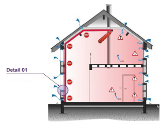
Illustration of the principle of the airtight and continuous “air barrier” [1]
The red line forms the later air barrier. This procedure should be repeated for all floor plans and sections. For each exterior building component it has to be determined which layer of the building element will provide air tightness.
From Outline to Detail
The outline is followed by detail drawings of points of change in building components, material, or directions. Also mark the run of the air barrier in these detailed representations. Finally, plan where the airtight building component layers are lastingly connected airtight at their transitions.
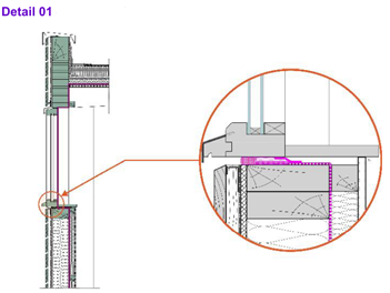
Example of a detail including the air barrier [1]
Avoiding Penetrations
The number of necessary penetrations of the air barrier (wiring, pipes, electrical outlets in the external walls) should be kept to a minimum.
Air barrier: materials and installation methods
Based on the planning and the execution plans, craftsmen can install the air barrier. During implementation, the manufacturer's instructions on the airtightness of the materials and their way of installation must be observed, such as a dry and dust-free substrate when using adhesive tapes, etc.
Checking for leaks at 50 Pascal induced pressure
When the air barrier is completed, create a pressure difference between inside and outside of the building of ca. 50 Pa negative pressure with the test equipment (blower door). To check for leaks at building components use your hand, a thermoanemometer, a fog generator or an infrared camera. Create a leakage report and / or mark the leakages so that they easily can be found and sealed by the craftsmen.
Final measurement
At the end of the construction process, the air tightness measurement is performed according to the relevant standards (e.g. ISO 9972 in Europe). This measurement serves to verify whether the air tightness of the building envelope defined at the beginning is achieved and meets the desired requirements.
Many countries have developed guidelines to build airtight, some of them are listed in [2].
References
[1] Carrié F.R., Jobert R., Leprince V., "AIVC Contributed Report 14: Methods and techniques for airtight buildings", AIVC, 2012
[2] Leprince V., Kapsalaki M., Carrié F.R., "AIVC Ventilation Information Paper (VIP) 37: Impact of Energy Policies on Building and Ductwork Airtightness", AIVC, 2017
How do you design for ductwork airtightness?
Leakage in ventilation duct systems is important to keep to a minimum in order to save energy and keep the designed performance for a good indoor air quality. The tightness can be built by quality products and a professional installation or be sealed off afterwards by a sealant which is transformed into a gaseous state using heated compressed air. The aerosolized particles then seal the whole leakage of the ventilation system.
To design ventilation duct fittings in the proper way it is important to have the right shape on each product both after production but also during transport and handling. Each product has to have purpose designed seals, all seals like tape or mastic made on the installation site are extremely hard to achieve in a professional manner.
The ducts and duct fittings like bends, connectors or transformations are normally not so difficult to achieve and there are some certification programs that guarantee that the system is the promised quality. Technical components like dampers, silencers, filter boxes are normally a bit more difficult and are sometimes produced by a company only focusing on this specific component where no certification program is available. In 2010 the standard EN 15727 Duct and ductwork components, leakage classification and testing was developed to help the ventilation business focus on airtightness for the whole system even if the components are produced by different suppliers.
The installation will be focused on in the standard EN 12599 handing over and the design and calculation will be addressed in EN 16798-3 performance requirements of ventilation.
At the installation phase it is important to follow the supplier installation instructions and use the proper recommended sealings, screws and clamps the right way. To test air tightness during the installation before the system is built in or insulated is also wise to be able to fix any possible problem. To have the installer himself test the system during the work will be very educational and will lead to professional, fast and insightful staff.
What is an air barrier?
A combination of materials within wall and roof assemblies which establish a continuous plane of airtightness in the building envelope. Its most important function is moisture control, but it also plays a significant role in energy efficiency, rain control and external noise protection. The system has to meet four requirements: a sufficiently low air permeance, continuity at all joints and intersections, strength against peak wind pressures, and the ability to meet these functions over the service life of the system (durability). These criteria apply to all air barrier components: boards, films, fasteners, gaskets, sealants, etc. Additional points to be considered in the design and assembly of air barrier systems are the accessibility for maintenance and the certification of specialised trades, in order to ensure that air barrier systems are installed at a consistent quality in practice [1].
References
[1] NRC, 1997. Air barrier systems for walls of low-rise buildings: performance and assessment. Canadian Construction Materials Centre, National Research Council Canada, Ottawa, Ontario.
See also
Is building airtightness testing mandatory?
Requirements depend on the country and the context of the measurement. Most EU countries include in their regulations either required or recommended minimum airtightness levels with or without mandatory testing. There are several countries (e.g.United Kingdom, France, Belgium, Ireland) where, by regulation, airtightness testing is mandatory for certain building types or in the case of specific programmes [1].
References
[1] Leprince V., Kapsalaki M., & Carrié F., R., “VIP 37: Impact of Energy Policies on Building and Ductwork Airtightness”. AIVC, 2017.
Is the building preparation for airtightness test identical for every country?
In most European countries the building preparation is based on ISO 9972 requirements. However, the interpretation of these requirements may differ from one country to another, and based on different building preparation rules.
Building preparation errors are probably the dominant source of uncertainty in an airtightness test. The reference testing protocol in Europe is described in ISO 9972, in the USA in ASTM 779-19, and in Canada in CGSB 149.10-2019. Nevertheless, ISO 9972 proposes 3 different methods (with different preparation requirements):
- Method 1: Test of the building in use
- Method 2: Test of the building envelope
- Method 3: Test of the building for a specific purpose according to a standard or policy in each country
Many countries have developed specific guidelines to detail or adapt to the ISO 9972 requirements.
A study has been performed to compare building preparation rules for airtightness testing in 11 European countries [1]. Information has been collected through a questionnaire sent to TAAC (TightVent Airtightness Associations Committee) members [2]. It has been found that building preparation differs significantly from one country to another and that methods 1 and 2 described in the standard are either too detailed or insufficiently described to fit the specificities of each country. This has supported the creation of “method 3” in ISO 9972:2015 (which is one of the major changes compared to former EN 13829:2000). "Method 3" needs to be defined at the national level which allows to adapt the measured extent and the building preparation to the purpose and context of the test. More specifically, it allows each country:
- to describe more precisely the basic principles of the preparation to avoid ambiguities; and
- to have some flexibility to specify rules consistent with their energy performance calculation method.
The main obstacles to harmonize pressurization test methods between countries are:
- In each country the test method shall be consistent with the energy performance calculation method. But there are significant differences in calculation methods between countries in the way airflow rates are taken into account.
- There are specific devices and construction traditions in each country that may require tailored rules.
Therefore, it is clear that building airtightness should not be compared between countries unless precaution is taken in the sample analyzed and in the interpretation of the results.
The figure below shows how 6 openings categorized as "other" in the standard are prepared in the countries asked in the above-mentioned study. It shows, for example, that in some countries the air exhaust of a clothes dryer will be left open while in others it will be sealed.
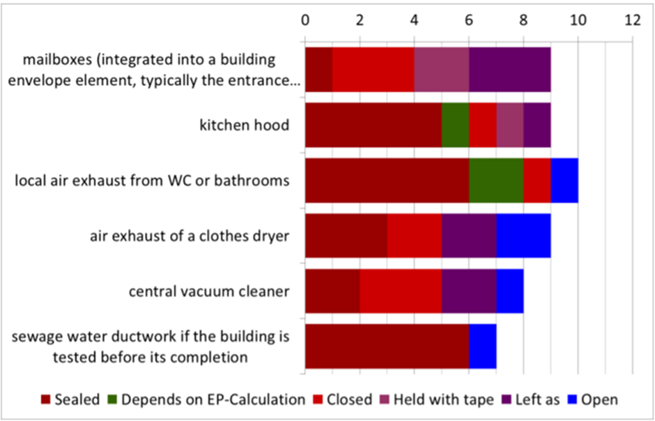
References
[1] Leprince V. & Carrié F.R, "Comparison of building preparation rules for airtightness testing in 11 European countries", 35th AIVC Conference "Ventilation and airtightness in transforming the building stock to high performance", Poznań, Poland, 2014
[2] TightVent Airtightness Associations Committee (TAAC), "TAAC Deliverables", Retrieved on April 6, 2022
What sort of certification programmes for ductwork airtightness exist?
Eurovent Certita Certification have a certification programme for rigid and semi-rigid ventilation ductwork systems divided into the following sub-programmes:
- Rigid metallic ductwork systems with circular cross-section (DUCT-MC);
- Rigid metallic ductwork systems with rectangular cross-section (DUCT-MR);
- Semi-rigid non-metallic ductwork systems predominantly made of plastics (DUCT-P);
Each sub-programme applies to ductwork systems fitted with integrated sealing solution as described in the Technical Certification Rules ECP-19.
This programme contains amongst other, airtightness and static gauge pressure limit criteria and is based on European standards.
The certification process is to periodically check the resilience of the company quality system by auditing manufacturing sites and the certified performances of a ventilation system by a third-party laboratory measurement.
The certification brings the supplier products, its technical documentation and quality resilience to a reliable level.
The DUCT program does not cover other types of ventilation ductwork elements like flexible ducts, double-wall ductwork or ductwork made of insulation ductboards.
The Swedish type approval for metallic ducts has been a very important driver for the ventilation business. The requirement based vision has driven the ventilation business since the beginning of the 1970’s to sustainable solutions with demands on airtightness and strength without a demand for sheet steel thickness. This has led to airtight energy efficient duct work solutions with as little material as possible.
The Swedish Type approval issued by governmental Boverket is only valid in Sweden but has been widely used in other countries as well. There are two Swedish bodies accredited by SWEDAC to issue type approvals, RISE and Kiwa.
Finland has developed their own approval based on the Swedish type approval and is handled by the Finnish Ministry of Environment, and Eurofins Expert Service Oy is authorized by the Finnish Ministry of Environment to issue type Approvals for building products.
What is a Blower Door?
A blower door is a device used to measure the airtightness of buildings.
It can also be used to measure air leakage between building zones, to locate leaks in ductwork and to help physically locate air leakage sites in the building envelope.
There are three primary components to a blower door:
- a calibrated, variable-speed blower or fan, capable of inducing a range of airflows sufficient to pressurize and depressurize a variety of building sizes,
- a pressure measurement instrument, called a manometer, to simultaneously measure the pressure differential induced across the face of the fan and across the building envelope, as a result of fan airflow, and
- a mounting system, used to mount the fan in a building opening, such as a door or a window.
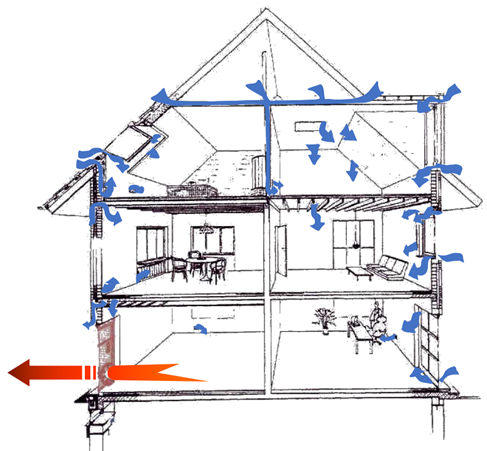
Source: BlowerDoor GmbH
References
[1] M. Limb, “Technical note AIVC 36- Air Infiltration and Ventilation Glossary,” International Energy Agency energy conservation in buildings and community systems programme, 1992.
[2] "Blower Door Tests | Department of Energy". Energy.gov. 2012-04-02
What does the n50 value mean?
n50 is a number used to quantify building airtightness. It gives the air change rate occurring as a result of air leakage through the building envelope when an air pressure difference of 50 Pa exists between inside and outside. This air change rate is the leakage volume airflow rate in m3/h measured at 50 Pa pressure difference divided by the buildings’ internal volume. It is expressed in h-1.
What are the impacts of poor envelope airtightness on ventilation, indoor air quality and building damage?
Air infiltration adds to the quantity of air entering the building but may also distort the intended ventilation air flow pattern to the detriment of overall indoor air quality and comfort. The consequences are inferior performance, excessive energy consumption, and inability to provide adequate heating (or cooling) [1].
Because air infiltration is uncontrolled, poor envelope airtightness may affect:
- Indoor air quality: Some rooms may be largely under-ventilated while other are over-ventilated as a consequence of distorted air flow patterns. Also air infiltration through the building envelope may bring inside pollutants from outside and from building product emissions. In case of balanced mechanical ventilation with filters to improve the IAQ, a poor airtightness may decrease the positive effect of filters.
- Energy use: Air leakage may inadequately increase the total ventilation airflow rate; or it may decrease the relative impact of heat recovery (in case of systems with heat recovery devices, the unit will only recover heat on the airflow passing through it).
- Moisture performance: air leaking through the envelope from a warm, humid environment to a cold environment, may cause condensation damage as it flows along materials with a temperature below its dew point. In cold climates condensation damage may occur in materials at the outside of the thermal insulation when air exfiltrates, while in warm climates damage may occur at the inside of the insulation when air infiltrates.
- Acoustic performance: airborne sound may propagate through leakages. It is found that sound transmission loss can be degraded by up to 15 dB under field conditions, mainly because of sound leaks.
- Ventilation: if a building is equipped with a correctly designed and installed ventilation system (whether natural, mechanical or hybrid), better building airtightness converges with better indoor air quality because the ventilation system operates more efficiently. Building leaks cause uncontrolled airflows and potentially poorly ventilated rooms although the total building air exchange rate may be sufficient [2]. A good building airtightness is specifically important for the correct operation of ventilation systems which rely on the transfer of air from rooms where fresh air is supplied to rooms where polluted air is extracted.
References
[1] Liddament M.W., 1996. A Guide to Energy Efficient Ventilation. AIVC, 1996.
[2] L. Mouradian and X. Boulanger, “QUAD-BBC, Indoor Air Quality and ventilation systems in low energy buildings,” AIVC Newsletter No2, June 2012
What is TAAC? How can I be involved?
TAAC is the TightVent Airtightness Associations Committee, launched in September 2012 by the TightVent Europe platform, with the primary goal to bring together national associations and experts in order to promote reliable testing/inspection and reporting procedures.
The scope of TAAC includes various aspects such as: building & ductwork airtightness requirements in the countries involved; competent tester schemes in the countries involved; applicable standards and guidelines for testing; inspection of ventilation systems; collection of relevant guidance and training documents; share of knowledge and experience; and information on ongoing research work in the field of building and ductwork airtightness.
At present the participants are from Belgium, Czech Republic, Estonia, France, Germany, Hungary, Ireland, Latvia, Netherlands, Poland, Portugal, Spain, Sweden, Switzerland, UK and the US.
In case you are interested to join this initiative, please write an email to: info@tightvent.eu.
Links:
For more information please see:
- About TAAC: https://tightvent.eu/taac
- TAAC participants: https://tightvent.eu/taac/taac-participants
- TAAC deliverables (publications, webinars etc.): https://tightvent.eu/taac/deliverables
- Becoming a Tightvent partner (for companies): https://tightvent.eu/contact
- Becoming a TAAC member: https://tightvent.eu/taac/contact-join
The text and images of this webpage is available for modification and reuse under the terms of the Creative Commons Attribution-Sharealike 3.0 Unported License and the GNU Free Documentation License (unversioned, with no invariant sections, front-cover texts, or back-cover texts).